Method of Forming a Polymer Component

a polymer and component technology, applied in the field of polymer components, can solve the problems of poor quality of oxidized polymer, deterioration of mechanical properties of polymer, etc., and achieve the effects of preventing oxidation in use, reducing the amount of oxidation of polymer, and high contact stress in us

Active Publication Date: 2011-06-23
JOINTMEDICA LTD
View PDF94 Cites 175 Cited by
  • Summary
  • Abstract
  • Description
  • Claims
  • Application Information

AI Technical Summary

Benefits of technology

[0021]It is a great advantage of the present invention that cross-linking is not inhibited by having a high concentration of antioxidant. In fact, high concentrations of antioxidant can be advantageous in significantly reducing the amount of oxidation of the polymer. Furthermore, the applicants have found that the same cross-link density can be obtained using two very different amounts of antioxidant and so it has been determined that a high concentration of antioxidant on the polymer particle surfaces does not inhibit cross-linking.
[0022]The applicants also believe that the antioxidant may not be needed after the consolidation step, since the heat that may be required for consolidation may eliminate all free radicals. However, if a low dose of irradiation was to be used on the consolidation (e.g. to sterilise the final component), free radicals would be formed during this process and the antioxidant would neutralise these free radicals and prevent oxidation in use. Further, high contact stress in use can cause breakdown of some cross-links and exposure of free radicals. The antioxidant in the final product can therefore act as a safeguard preventing oxidation in this eventuality by neutralising any free radicals formed.
[0023]In certain embodiments of the present invention, the antioxidant (e.g. vitamin E) may constitute up to 3% of the weight of the mixture. In particular embodiments, the antioxidant (e.g. vitamin E) may constitute 0.1%, 0.5%, 1%, 2%, or 3% of the weight of the mixture.
[0024]The step of forming the irradiated mixture into a consolidated component may comprise the use of heat and / or pressure (e.g. by performing hot or cold compression moulding). Where heat is employed in the consolidation process, it will be understood that any free radicals present in the irradiated mixture will be eliminated or minimised, thus obviating the need for re-melting or annealing and thereby maintaining good mechanical properties of the consolidated material. Furthermore, as the consolidated component contains antioxidant, any free radicals generated during future use of the component will tend to be neutralised by the antioxidant.
[0025]The polymer particles may be provided in the form of a resin (e.g. comprising powder, flakes and / or small pellets) or a hydrogel (e.g. comprising a polymer capable of absorbing water).
[0026]The antioxidant may be provided in the form of a liquid, powder, solution or suspension. For example, a powder (or liquid) antioxidant may be dissolved in a solvent such as alcohol to increase the volume of the antioxidant containing element and allow it to more easily coat the polymer particles. The solvent may be evaporated off after the blending. Alternatively, for example for insoluble antioxidants, the bulk of the antioxidant containing element can be increased by placing the antioxidant in a suspension of liquid (e.g. water).

Problems solved by technology

However, the mechanical properties of the polymer have been found to deteriorate as a result of re-melting.
The problem with this approach, however, is that the very large surface area of the polyethylene resin permits oxidation of the material during irradiation, even when performed in a reduced oxygen atmosphere.
The resulting oxidized polymer is of a poor quality since it will be susceptible to severe wear and fracture due to mechanical weakening.

Method used


Image

  • Method of Forming a Polymer Component
  • Method of Forming a Polymer Component
  • Method of Forming a Polymer Component

Examples


Embodiment Construction

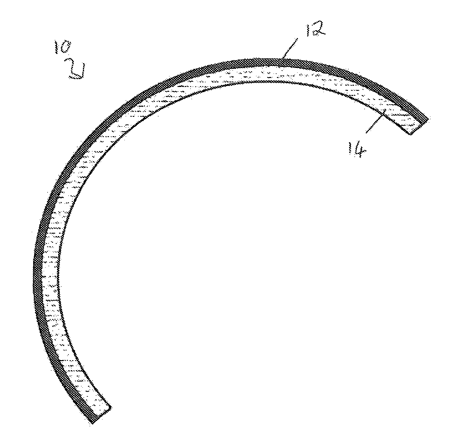
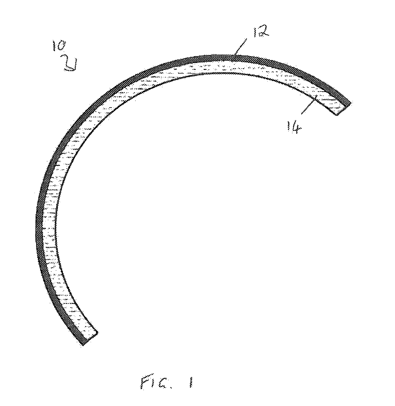
[0288]With reference to FIG. 1, there is illustrated a central cross-section of a proposed acetabular cup prosthesis 10 having a relatively thin (e.g. 1 mm) hemi-spherical metal outer shell 12 and a co-centred relatively thick (e.g. 2 mm) hemi-spherical polymer inner liner 14. In this case, the polymer inner liner or shell 14 is glued by an adhesive (not shown) to the inner surface of the metal outer shell 12. It will be noted that inner diameter to outer diameter difference of the cup 10 is 6 mm—the cup 10 having a thickness of 3 mm at each side.

[0289]While such a thin-walled acetabular cup prosthesis is desirable for hip resurfacing (where only a minimal amount of bone is removed to accommodate the implant), it has been proposed that insertion of the cup using a traditional 2 mm press-fit technique would lead to uncontrolled distortion and damage to the cup. Various aspects of the present invention therefore aim to address this problem.

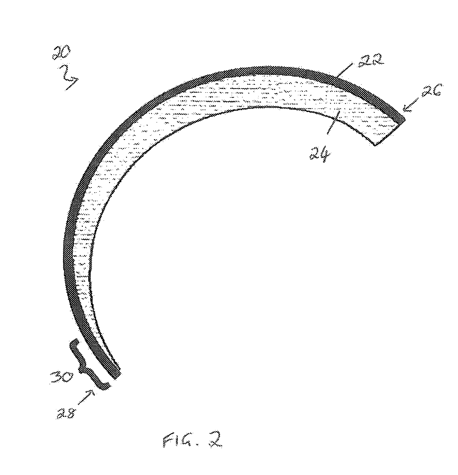
[0290]FIG. 2 shows a central cross-section of...


PUM

PropertyMeasurementUnit
diameteraaaaaaaaaa
diameteraaaaaaaaaa
diameteraaaaaaaaaa

Abstract

This invention relates to a method of forming a polymer component and comprises blending polymer particles with antioxidant to form a mixture in which the antioxidant coats the polymer particles, irradiating the mixture to cross-link the polymer particles therein and forming the irradiated mixture into a consolidated component. The invention also relates to a method of forming an articular surface for a prosthesis and a prosthesis having a polymer articular bearing surface wherein at least one pre-determined portion of the bearing surface is provided with cross-linked polymer bonds.

Description

CROSS REFERENCE TO RELATED APPLICATIONS[0001]This application claims the benefit of and priority to United Kingdom Patent Applications Serial Nos. 0922339.7 and 1000744.1, filed Dec. 21, 2009 and Jan. 18, 2010, respectively, the entire disclosures of each are incorporated by reference herein for all purposes.FIELD OF THE INVENTION[0002]This invention relates to a method of forming a polymer component. Particularly, but not exclusively, the invention relates to a method of forming a polymer component for a prosthesis such as an acetabular cup prosthesis for use in hip resurfacing.BACKGROUND TO THE INVENTION[0003]Hip resurfacing is commonly performed using acetabular cups and femoral components which are made from solid metal. However, it has been estimated that approximately 1% of patients who undergo such metal-on-metal hip resurfacing have a pseudo-tumour in the form of a soft tissue mass or large symptomatic effusion within 5 years. The symptoms of these pseudo-tumours include dis...

Claims


Application Information

Patent Timeline
Patent Type & Authority Applications(United States)
IPC IPC(8): A61F2/38B05D3/06B32B37/00B32B37/24
CPCA61F2002/30378B32B7/12A61F2/3094B32B3/00A61F2002/30986B32B2535/00A61F2002/30561C08J3/24A61F2002/30112A61F2002/30685A61F2002/30143A61F2/38A61F2230/0017A61F2230/0004A61F2220/0075A61F2/34A61F2002/30841A61F2220/0025A61F2220/005A61F2002/30971A61L27/14A61L27/505A61F2/30771A61F2002/3052A61F2002/4681B32B15/08A61F2002/344A61F2002/30026A61F2002/30462A61F2220/0033A61F2002/30352B32B1/00C08J2300/00A61F2002/30331A61F2/4609A61F2002/30878C08J3/00A61F2002/30904A61L27/50A61F2002/30448B23B3/00A61F2002/30205A61F2002/30207A61F2002/30324A61F2002/30889B29C43/003B29C43/146B29C2043/147B29C2043/148B29K2023/06B29K2105/0044B29L2031/7532B33Y80/00C08J3/28C08J2323/06C08K5/1545C08K2201/012
Inventor MCMINN, DEREK J.
Owner JOINTMEDICA LTD
Why Eureka
Try Eureka