
LED device and illuminating apparatus

a technology of led devices and led devices, which is applied in the direction of basic electric elements, electrical devices, semiconductor devices, etc., can solve the problems of reducing the luminous efficiency of the device, changing the color of the light emission, etc., and achieve the reduction of the luminous efficiency of the led device, the effect of preventing the degradation of the phosphor due to heat and moisture absorption or oxidation

Inactive Publication Date: 2010-04-29
NEC LIGHTING
View PDF6 Cites 53 Cited by
  • Summary
  • Abstract
  • Description
  • Claims
  • Application Information

AI Technical Summary

Benefits of technology

[0007]Thus, an object of the present invention is to provide an LED device and an illuminating apparatus capable of preventing a diminution in luminous efficiency and obtaining a predetermined light emission color.
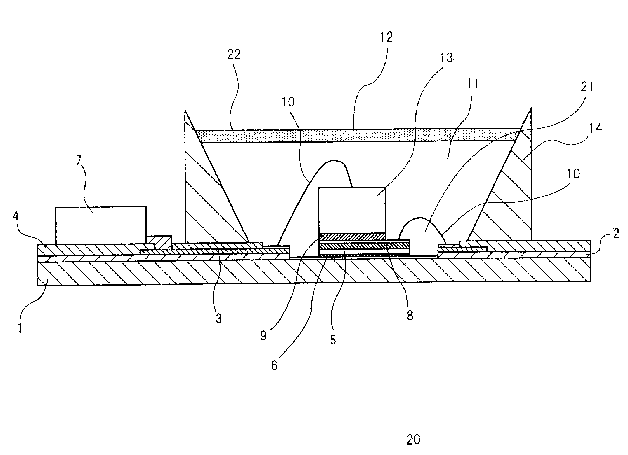
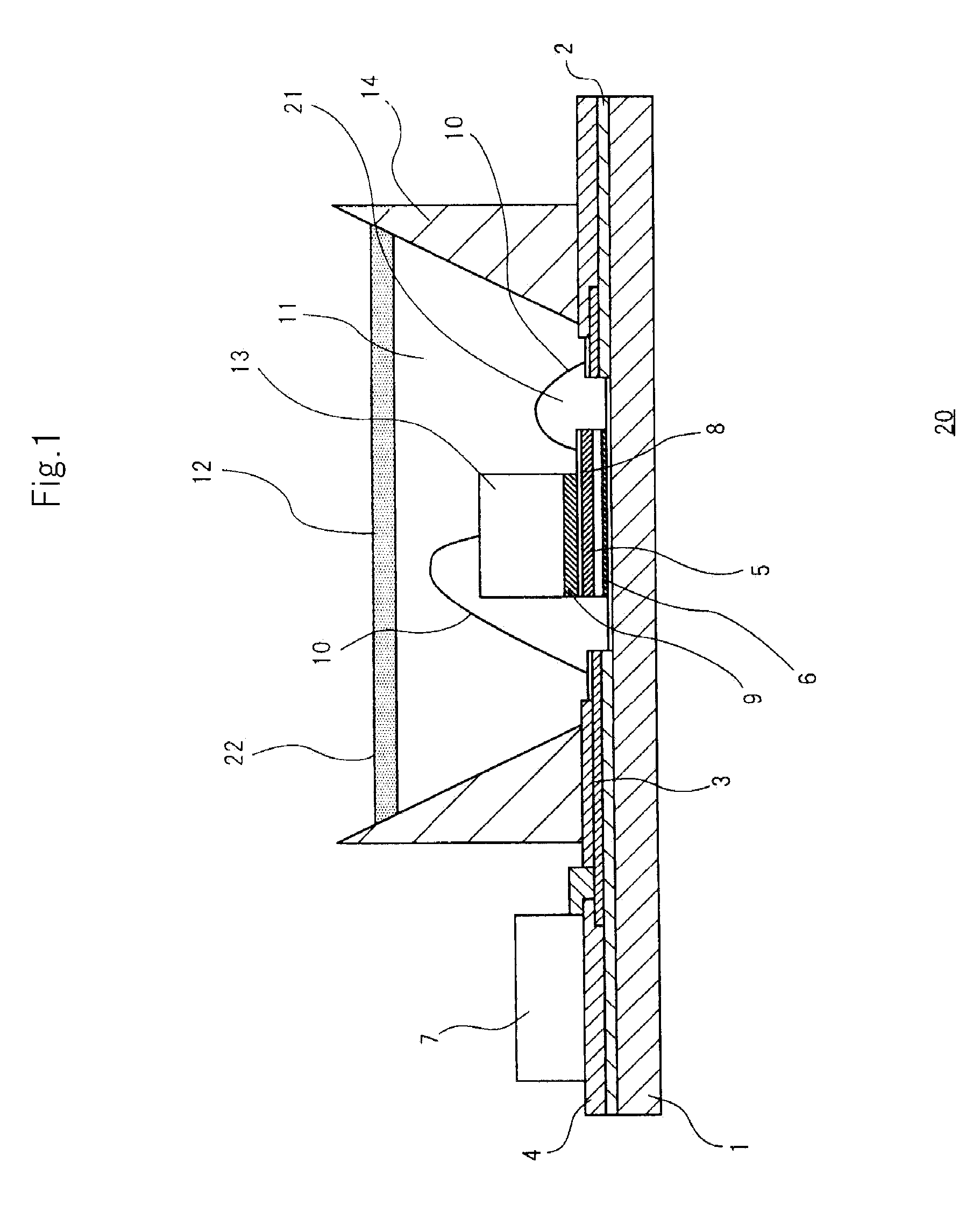
[0021]According to the present invention, because the phosphor is contained in the glass member, degradation of the phosphor due to moisture absorption or oxidation can be prevented. In addition, heat generated from the LED chip is released from the metal substrate and the glass member is disposed by the medium of the heat-resistant sealing resin having thermal resistance, degradation of the phosphor due to heat can thus be prevented. As a result, a diminution in the luminous efficiency of the LED device can be prevented and a predetermined light emission color can be obtained.

Problems solved by technology

1. Because the resin absorbs moisture, the phosphor absorbs moisture or is oxidized and thereby degraded. Thus, since the phosphor is degraded for a long time, the luminous efficiency of the device deteriorates.
2. Because a light emission wavelength of the phosphor is altered due to heat generated from the LED chip, the required light emission color is changed.

Method used


Image

  • LED device and illuminating apparatus
  • LED device and illuminating apparatus
  • LED device and illuminating apparatus

Examples


second embodiment

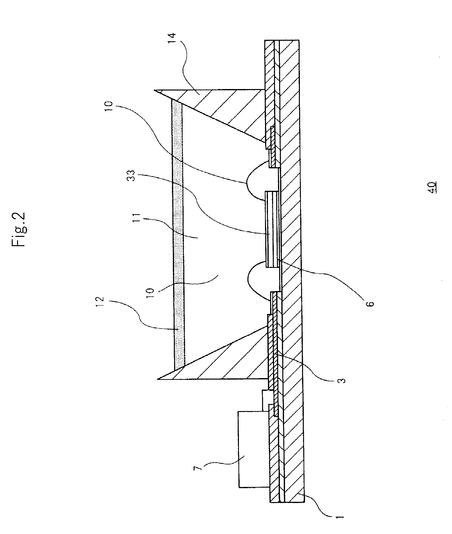
[0052]LED chip 33 of white LED device 40 according to this embodiment uses a configuration in which a P pole and an N pole are provided on its upper surface, and is mounted on metal substrate 1 without using a sub-mount therebetween. Other basic configuration is the same as that of the first embodiment, so its detailed description will be omitted.

[0053]A plated layer (e.g., a gold-plated layer) is formed on a lower surface of LED chip 33 where the P pole and the N pole are not formed, so as to be adapted to soldering. The lower surface of LED chip 33 faces to be bonded with metal substrate 1 by soft solder 6. The P pole and the N pole are electrically connected to the wiring layers 3 by the electrical connection wirings 10. Namely, in the present exemplary embodiment, as described above, the P pole and the N pole are formed on the upper surface of LED chip 33 and are not formed on the lower surface of LED chip 33, so insulation by a sub-mount is not necessary. Also, a hard solder fo...


PUM


Abstract

White LED device 20 includes LED chip 13 mounted on substrate 1 made of metal, sealing resin 11 that seals LED chip 13; and glass member 12 formed on sealing resin 11. Glass member 12 contains phosphor 22 and thermal conductivity of sealing resin 11 is lower than that of glass member 12.

Description

TECHNICAL FIELD[0001]The present invention relates to a light emitting diode (LED)-equipped LED device and an illuminating apparatus.BACKGROUND ART[0002]As an LED illuminating device that illuminates a display device performing color display using RGB color filters in relation to the present invention, a multi-color mixed type LED illuminating device is in use. The multi-color mixed type LED illuminating device illuminates white light by simultaneously making three RGB color LEDs emit light and performs color display with the white light and the color filters of the display device. However, the multi-color mixed type LED illuminating device has a problem in that each LED of the RGB colors emits light, a large number of LEDs are required to obtain the white light, thereby increasing the cost.[0003]As a solution to the problem of the multi-color mixed type LED illuminating device, for example, a phosphor color mixed type LED illuminating device is disclosed in Japanese Patent Publicat...

Claims


Application Information

Patent Timeline
Patent Type & Authority Applications(United States)
IPC IPC(8): H01L33/00H01L33/50H01L33/56
CPCH01L25/167H01L33/56H01L33/507H01L33/501H01L2224/48091H01L2224/73265H01L2924/0002H01L2924/19107H01L2224/2612H01L2924/00014
Inventor UEJI, YOSHINORI
Owner NEC LIGHTING
Learn More