Organic electroluminescent device

a technology of electroluminescent devices and organs, which is applied in the direction of discharge tubes/lamp details, discharge tubes luminescnet screens, other domestic articles, etc., can solve the problems of long exciton lifetime, triplet-triplet annihilation, and energy of two triplet excitons lost in heat or vibration instead of releasing photons, so as to improve luminance efficiency and improve luminance efficiency of phosphorescent emissive layers.

Active Publication Date: 2009-01-06
OPTRONIC SCI LLC
View PDF14 Cites 34 Cited by
  • Summary
  • Abstract
  • Description
  • Claims
  • Application Information

AI Technical Summary

Benefits of technology

[0012]It is therefore an object of the present invention to provide an organic electroluminescent device (OELD) capable of emitting visible phosphorescence and visible fluorescence at the same time. Because the luminance efficiency of the phosphorescent emissive layer is better than that of the fluorescent emissive layer, the luminance efficiency of the organic electroluminescent device of the present invention is better than that of the conventional organic electroluminescent device having only the fluorescent host-dopant system (such as a fluorescent device). Moreover, because the concentration of the phosphorescent excitons is diluted by the fluorescent excitons, the colliding probability of the triplet excitons is decreased effectively, avoiding the triplet-triplet annihilation. The declination of the luminance efficiency of the organic electroluminescent device of the present invention in high operating brightness is therefore restrained. As a result, the brightness and the luminance efficiency of the organic electroluminescent device of the present invention are much better than those of the conventional phosphorescent devices.

Problems solved by technology

Because the host material in the excited state is unstable, the host material certainly returns to the ground state and transfer energy to the dopants.
However, the long exciton lifetime is a disadvantage of the phosphorescent host-dopant system.
Therefore, the long staying time of the triplet excitons in the emissive layer results in triplet-triplet annihilation.
In other words, one triplet exciton in the excited state tends to collide with another triplet in the excited state, resulting in the energy of the two triplet excitons lost in the form of heat or vibration instead of releasing photons.

Method used


Image

  • Organic electroluminescent device
  • Organic electroluminescent device
  • Organic electroluminescent device

Examples


first embodiment

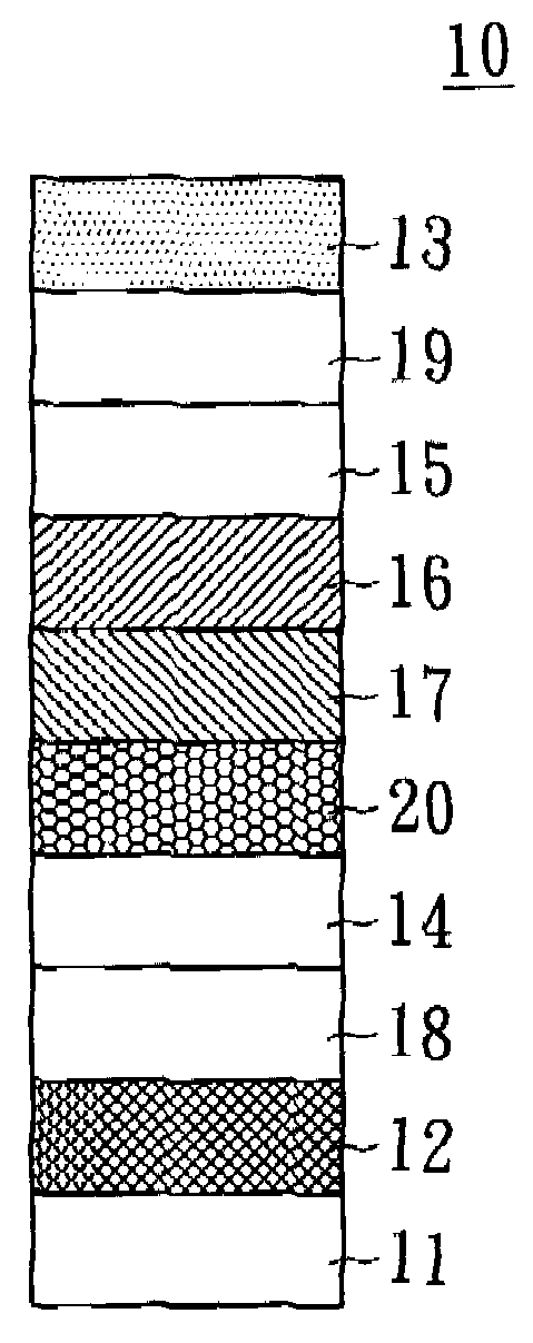
[0027]Referring to FIG. 1, a sectional view of an organic electroluminescent device (OELD) according to the first embodiment of the present invention is provided. The organic electroluminescent device includes an organic light emitting diode (OLED) and a polymer light emitting diode (PLED). The OLED is illustrated in the present embodiment of the invention. However, the skill revealed in the present embodiment of the invention can be applied to PLED as well.

[0028]In FIG. 1, the organic electroluminescent device 10 includes a substrate 11, a first electrode 12, a second electrode 13, a hole transport layer 14, an electron transport layer 15 and at least two emissive layers. The first electrode 12 (such as anode) and the second electrode 13 (such as cathode) opposite to the first electrode 12 are disposed over the substrate 11. The hole transport layer 14 is disposed between the first electrode 12 and the second electrode 13. The electron transport layer 15 is disposed between the sec...

second embodiment

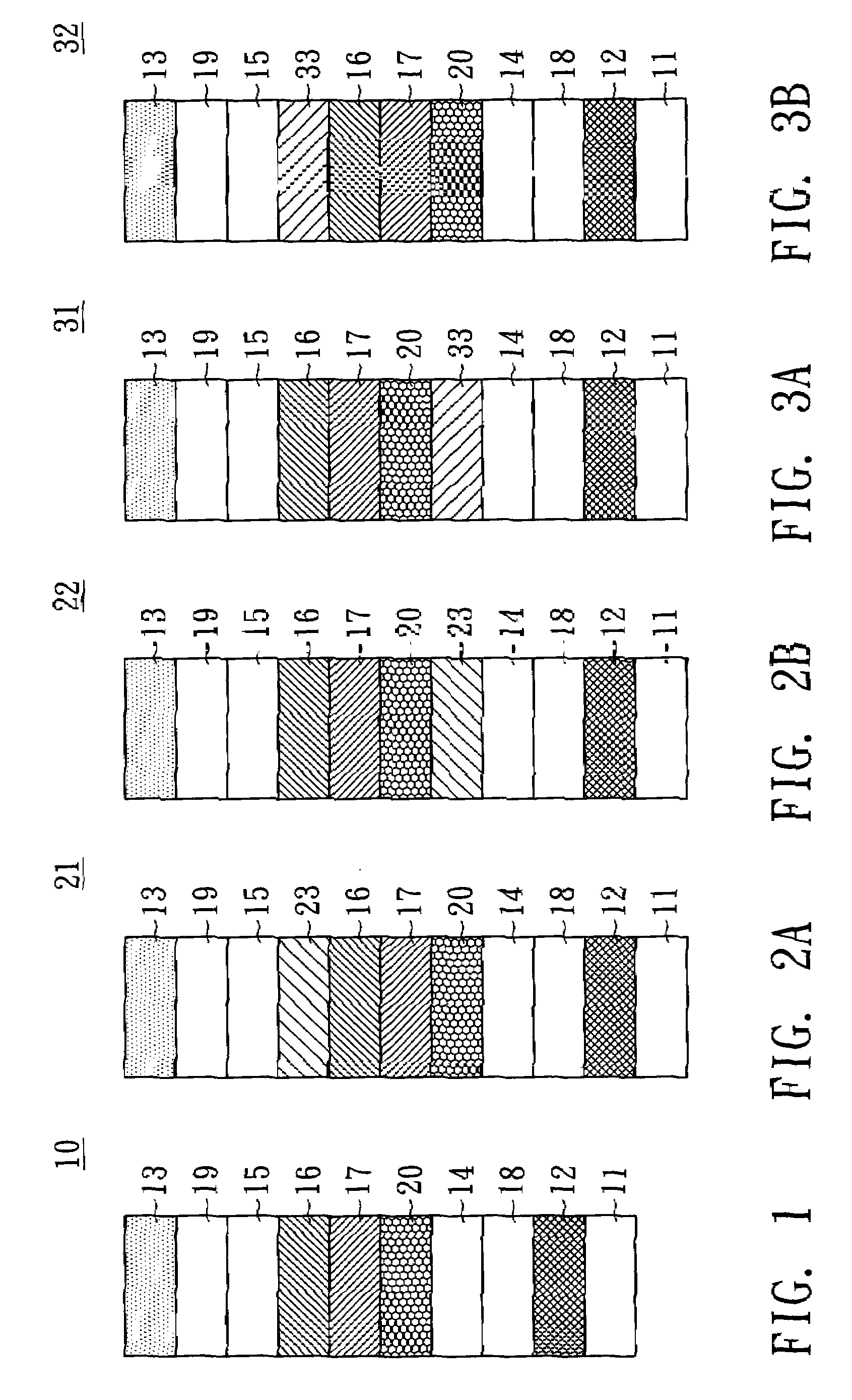
[0042]Referring to FIG. 2A-2B, cross-sectional views of organic electroluminescent devices according to the second embodiment of the present invention are illustrated. Compared with the organic electroluminescent device 10 of the first embodiment of the present invention, the organic electroluminescent devices 21 and 22 of the present embodiment of the invention further include the second fluorescent emissive layer 23. The same other elements using the same reference numbers are not illustrated redundantly.

[0043]In FIG. 2A, the second fluorescent emissive layer 23 is disposed between the first fluorescent emissive layer 16 and the electron transport layer 15.

[0044]In FIG. 2B, the second fluorescent emissive layer 23 is disposed between the first phosphorescent emissive layer 17 and the hole transport layer 14. In other words, the second fluorescent emissive layer 23 is disposed between the exciton blocking layer 20 and the hole transport layer 14.

[0045]However, a person having ordin...

third embodiment

[0047]Referring to FIG. 3A-3B, two cross-sectional views of organic electroluminescent devices according to the third embodiment of the present invention are illustrated. Compared with the organic electroluminescent device 10 of the first embodiment of the present invention, the organic electroluminescent devices 31 and 32 of the present embodiment of the invention further include the second phosphorescent emissive layer 33. The same other elements having the same reference numbers are not illustrated redundantly.

[0048]In FIG. 3A, the second phosphorescent emissive layer 33 is disposed between the first phosphorescent emissive layer 17 and the hole transport layer 14. In other words, the second phosphorescent emissive layer 33 is disposed between the exciton blocking layer 30 and the hole transport layer 14.

[0049]In FIG. 3B, the second phosphorescent emissive layer 33 is disposed between the first fluorescent emissive layer 16 and the electron transport layer 15. The organic electro...


PUM


Abstract

An organic electroluminescent device (OELD) is provided. The OELD includes a substrate, a first electrode, a second electrode, a hole transport layer, an electron transport layer and two emissive layers. The first electrode and the second electrode are disposed over the substrate. The hole transport layer is disposed between the first electrode and the second electrode. The electron transport layer is disposed between the second electrode and the hole transport layer. The emissive layers are disposed between the hole transport layer and the electron transport layer. One of the emissive layers is a fluorescent emissive layer and another one of the emissive layers is a phosphorescent emissive layer. The visible light of the fluorescent emissive layer and the phosphorescent emissive layer are not absorbed by each other and the visible light spectrums of the fluorescent emissive layer and the phosphorescent emissive layer are not affected by each other.

Description

[0001]This application claims the benefit of Taiwan application Serial No. 094109031, filed Mar. 23, 2005, the subject matter of which is incorporated herein by reference.BACKGROUND OF THE INVENTION[0002]1. Field of the Invention[0003]The present invention relates in general to an organic electroluminescent device and, more particularly, to an organic electroluminescent device capable of emitting visible phosphorescence and emitting visible fluorescence at the same time.[0004]2. Description of the Related Art[0005]A conventional organic electroluminescent device (OELD) is a multi-layer structure including a substrate, an anode, a cathode, a hole injection layer, a hole transport layer, an electron transport layer, an electron injection layer and an emissive layer. The anode, the hole injection layer, the hole transport layer, the emissive layer, the electron transport layer, the electron injection layer and the cathode are disposed on the substrate orderly from bottom to top. The em...

Claims


Application Information

Patent Timeline
Patent Type & Authority Patents(United States)
IPC IPC(8): H01J1/62H01J63/04H05B33/00
CPCC09K11/06H01L51/5036H05B33/14H01L51/0051H01L51/0054H01L51/006H01L51/0065Y10S428/917H10K85/611H10K85/653H10K85/622H10K85/633H10K50/125
Inventor LIU, TSWEN-HSINTSAI, TZE-CHIEN
Owner OPTRONIC SCI LLC
Why Eureka
Try Eureka