Anisotropic conductive adhesive and method for manufacturing same, light-emitting device and method for manufacturing same

a technology of anisotropic conductive adhesive and manufacturing method, which is applied in the direction of metal/alloy conductors, conductors, vacuum evaporation coating, etc., can solve the problems of difficult to enhance production efficiency, long time, etc., to reduce the light emission efficiency of light-emitting elements, reduce time consumption, and reduce time consumption

Inactive Publication Date: 2015-02-05
DEXERIALS CORP
View PDF3 Cites 36 Cited by
  • Summary
  • Abstract
  • Description
  • Claims
  • Application Information

AI Technical Summary

Benefits of technology

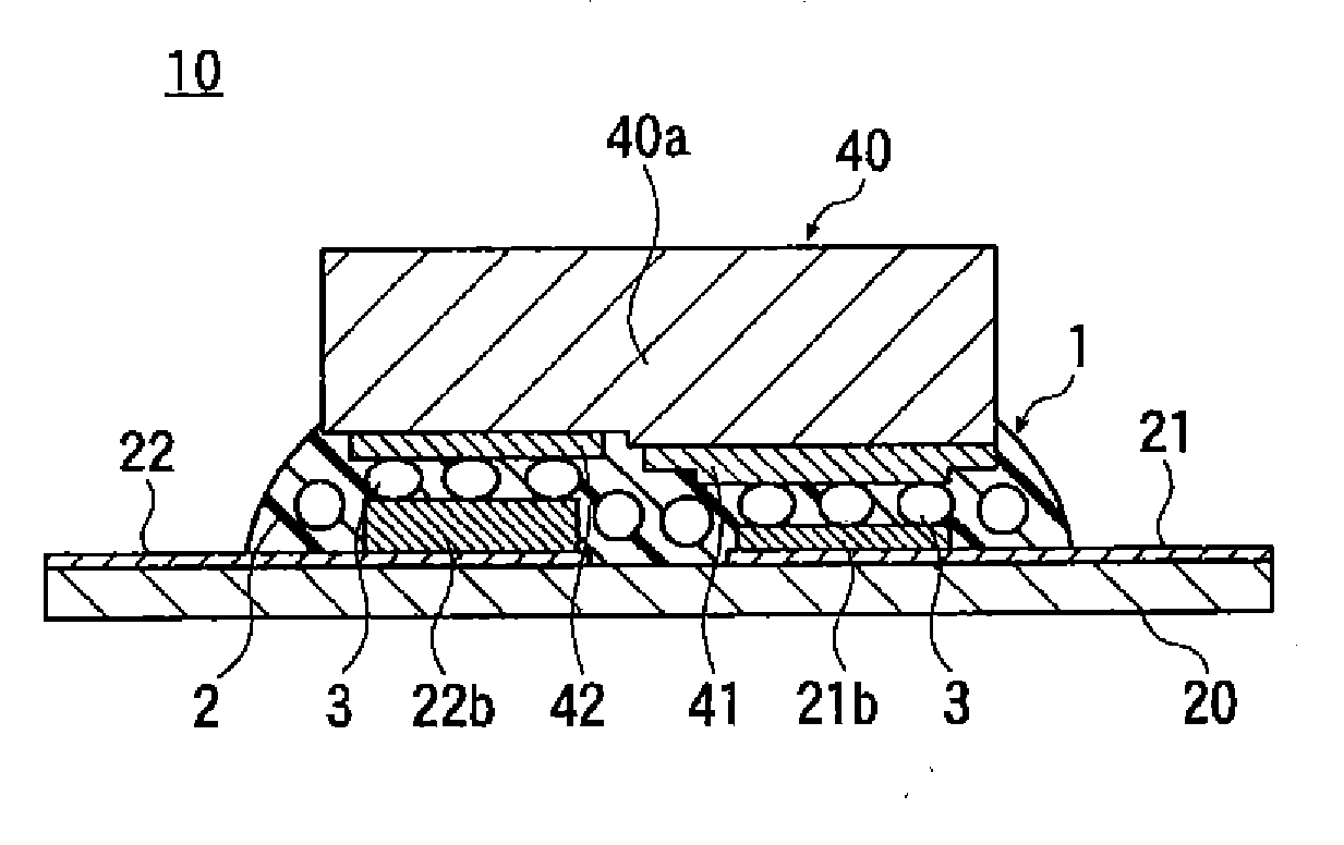
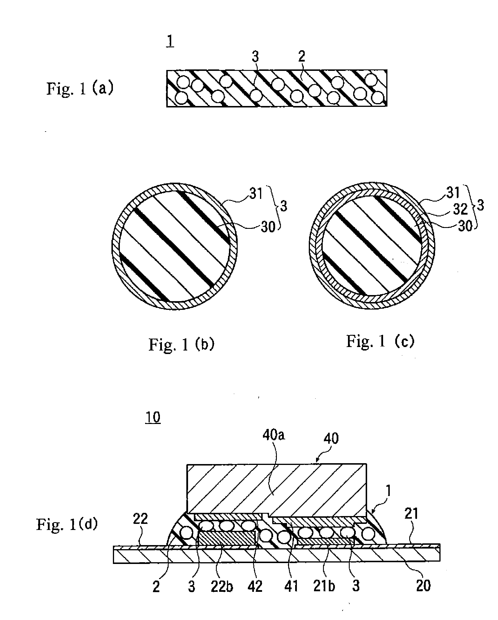
[0029]In the present invention, because the conductive particle of the anisotropic conductive adhesive has a light reflective metal layer made of metal including silver, gold, and hafnium on the surface of the resin particle as a core, accordingly the light reflective metal layer has a reflection rate similar to that of a silver, and thus, it is possible to suppress adsorption of light by the anisotropic conductive adhesive as a minimum.
[0030]Consequently, when the anisotropic conductive adhesive of the present invention is used to mount the light-emitting element on the wiring substrate, it is possible to provide the light-emitting device that can efficiently take out light without reducing the light emission efficiency of the light-emitting element.
[0031]In the anisotropic conductive adhesive of the present invention, because the light reflective metal layer of the conductive particle includes gold and hafnium of which migration does not easily occur is, it is possible to enhance migration resistance.
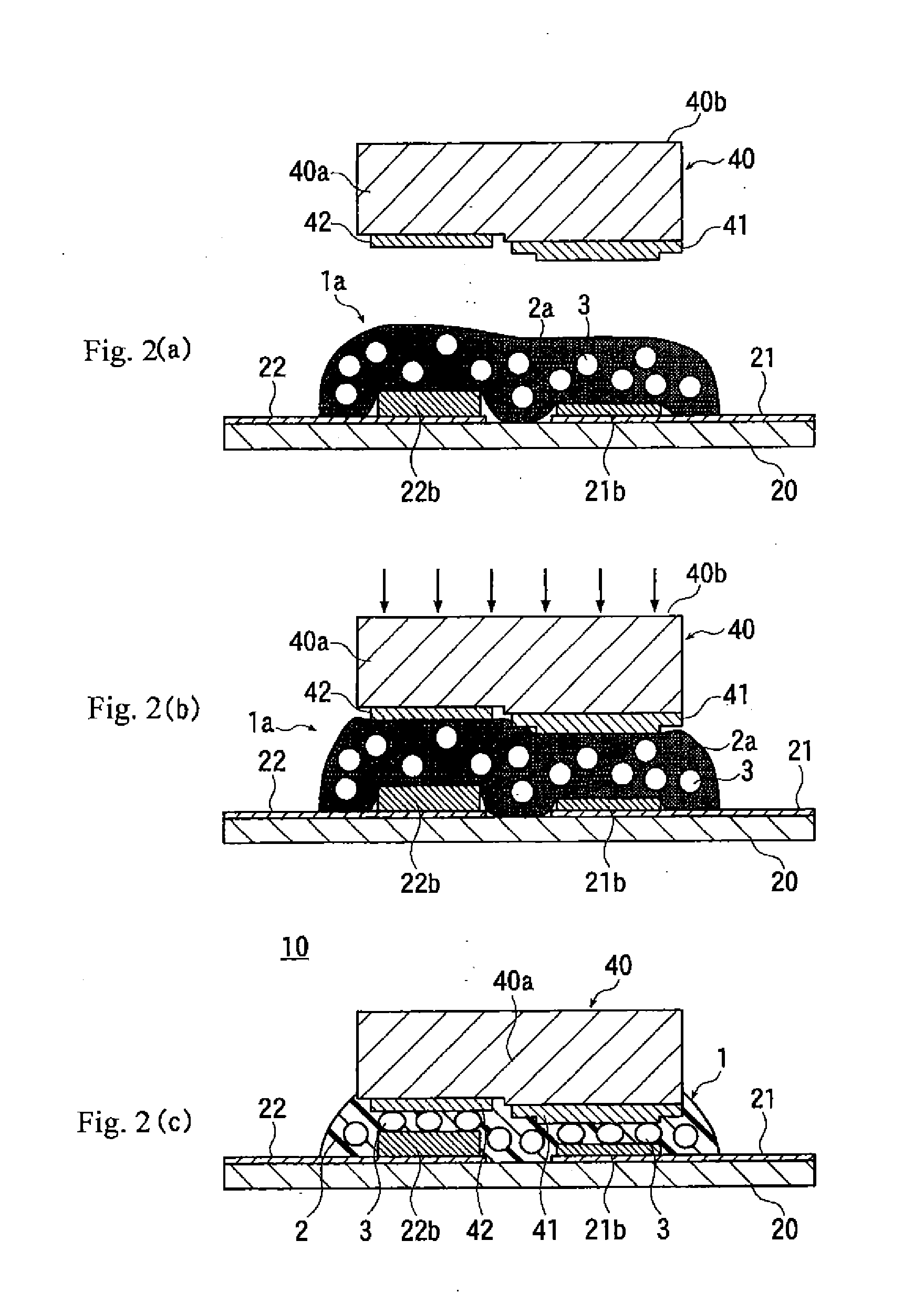
[0032]On the other hand, according to the method of the present invention, because the light-emitting device which provides the significant effects discussed above can be manufactured by the arrangement of the anisotropic conductive adhesive and the simple and rapid thermal compression process, it is possible to significantly enhance the production efficiency.
[0033]According to the present invention, it is possible to provide the technology of an anisotropic conductive adhesive using conductive particles where Ag based metal is used as a conductive layer and having high light reflectance and excellent migration resistance.

Problems solved by technology

However, there are various problems in the conventional technologies as discussed above.
In this method, because the die bonding adhesive 110 and 111 are cured using an oven, the curing time is long, and it is difficult to enhance the production efficiency.
Furthermore, in this method, because the sealing resin 126 and 127 is cured using an oven, the curing time is long, so that it is difficult to enhance the production efficiency.
However, because silver is a chemically unstable material, it disadvantageously easily undergoes oxidation and sulfurization, and after thermal compression, migration occurs by energization, and thus, the adhesion strength is disadvantageously degraded by a break in a wiring part and the degradation of an adhesive.
Although coating of the surface of the conductive particles with this Ag-based thin film alloy enhances the corrosion resistance and the migration resistance, when the Ag-based thin film alloy is used as the outermost layer, and nickel, for example, is used as a foundation layer, the reflectance of nickel is lower than that of Ag, and thus, there is a problem that the reflectance of the whole of the conductive particles is reduced, for examples, see JPA No. 2005-120375, JPA No.

Method used


Image

  • Anisotropic conductive adhesive and method for manufacturing same, light-emitting device and method for manufacturing same
  • Anisotropic conductive adhesive and method for manufacturing same, light-emitting device and method for manufacturing same
  • Anisotropic conductive adhesive and method for manufacturing same, light-emitting device and method for manufacturing same

Examples


examples

[0099]Although the present invention will be specifically discussed below using examples and comparative examples, the present invention is not limited to the following examples.

[0100]

[0101]An adhesive composition is prepared using 100 weight parts of an epoxy resin (sold under the name “CPEL2021P” made by Daicel chemical Industries, Ltd.), 100 weight parts of methylhexahydrophthalic anhydride (sold under the name “MH-700” made by New Japan Chemical Co., Ltd.) as a curing agent, 2 weight parts of a curing accelerator (sold under the name “2E4MZ” made by Shikoku Chemicals Corporation) and toluene as a solvent.

[0102]

example particle 1

[0103]A light reflective metal layer made of silver alloy (silver:gold:hafnium=54.5:27.3:18.2) having a thickness of 0.2 μm is formed by a sputtering method on the surface of resin particles (sold under the name “Art Pearl J-6P” made by Negami Chemical Industrial Co., Ltd.) made of a cross-linked acrylic resin having an average particle diameter of 5 μm.

[0104]In this case, as a sputtering apparatus, a powder sputtering apparatus made by Kyouritu Ltd. is used, and as a sputtering target, an Ag—Au—Hf alloy target made by a dissolution and casting method is used.

example particle 2

[0105]An example particle 2 was manufactured with the same condition as the condition of the example particle 1 except the composition ratio of the light reflective metal layer (silver:gold:hafnium=50:10:40).


PUM

PropertyMeasurementUnit
peak wavelengthaaaaaaaaaa
particle diameteraaaaaaaaaa
thicknessaaaaaaaaaa

Abstract

an anisotropic conductive adhesive which uses conductive particles where a silver-based metal is used as a conductive layer, having high light reflectance and excellent migration resistance is provided. The anisotropic conductive adhesive includes light reflective conductive particles in an insulating adhesive resin. The light reflective conductive particle includes a light reflective metal layer made of a metal alloy including silver, gold and hafnium formed on the surface of a resin particle as a core by sputtering method. The light reflective metal layer is preferably formed having a composition ratio of a silver of at least 50% by weight to at most 80% by weight: a gold of at least 10% by weight to at most 45%: a hafnium of at least 10% by weight to at most 40% by weight, and a total ratio does not exceed 100% by weight.

Description

[0001]This application is a continuation of International Application No. PCT / JP2013 / 61318, filed on Apr. 16, 2014, which claims priority to Japan Patent Application No. 2012-094141, filed on Apr. 17, 2012. The contents of the prior applications are herein incorporated by references in their entireties.BACKGROUND[0002]The present invention generally relates to an anisotropic conductive adhesive, and more particularly relates to a technology on an anisotropic conductive adhesive used for flip-chip mounting of semiconductor elements (such as, an LED (light-emitting diode)) on a wiring substrate.[0003]In recent years, attention has been focused on an optical functional element using an LED.[0004]In such an optical functional element, for example, in order to reduce its size, flip-chip mounting is performed in which an LED chip is directly mounted on a wiring substrate.[0005]As the method of performing the flip-chip mounting of an LED chip on a wiring substrate, as shown in FIGS. 4(a) t...

Claims


Application Information

Patent Timeline
Patent Type & Authority Applications(United States)
IPC IPC(8): C09J9/02C23C14/14H01L33/00H01L33/46H01L33/62
CPCC09J9/02H01L33/46H01L33/62H01L2933/0066C23C14/14H01L2933/0025H01L2933/0033H01L33/005C08J3/128C08K3/08C08K9/12C09J11/00C22C5/06H01B1/22H01L24/06H01L24/29H01L24/32H01L24/83H01L2224/0401H01L2224/06102H01L2224/13144H01L2224/1403H01L2224/16238H01L2224/2929H01L2224/2939H01L2224/29439H01L2224/29444H01L2224/29455H01L2224/32225H01L2224/48091H01L2224/48227H01L2224/49107H01L2224/73265H01L2224/81192H01L2224/83101H01L2224/83192H01L2224/83851H01L2924/07802H01L2924/07811H01L2924/12041H01L2924/00014H01L2924/00C09J201/00
Inventor NAMIKI, HIDETSUGUKANISAWA, SHIYUKIUMAKOSHI, HIDEAKIAOKI, MASAHARUISHIGAMI, AKIRA
Owner DEXERIALS CORP
Why Eureka
Try Eureka