Light-emitting diode

a diode and light-emitting technology, applied in the direction of basic electric elements, electrical equipment, semiconductor devices, etc., can solve the problems of degrading the luminous efficiency of the led and the brightness of the led

Inactive Publication Date: 2011-08-09
FOXSEMICON INTEGRATED TECH INC
View PDF7 Cites 35 Cited by
  • Summary
  • Abstract
  • Description
  • Claims
  • Application Information

AI Technical Summary

Benefits of technology

[0005]Generally, an LED includes a substrate, an LED chip disposed on the substrate, and a light pervious encapsulation covering the LED chip. When the LED chip emits light, the light eventually passes through the light pervious encapsulation. Usually, a bowl or cup shaped space is defined in the substrate for receiving the LED chip. An intensity distribution of the LED can be adjusted according to the design of the bowl or cup shaped space. However, light emitted from the LED chip may be internally reflected many times within the space before passing through the light pervious encapsulation. As a result, the brightness of the LED is decreased and the luminous efficiency of the LED is degraded.

Problems solved by technology

As a result, the brightness of the LED is decreased and the luminous efficiency of the LED is degraded.

Method used


Image

  • Light-emitting diode
  • Light-emitting diode
  • Light-emitting diode

Examples


Embodiment Construction

[0014]Reference will now be made to the drawings to describe in detail the preferred embodiments of the present light-emitting diode.

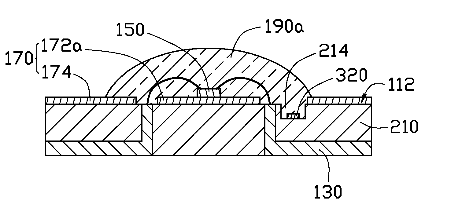
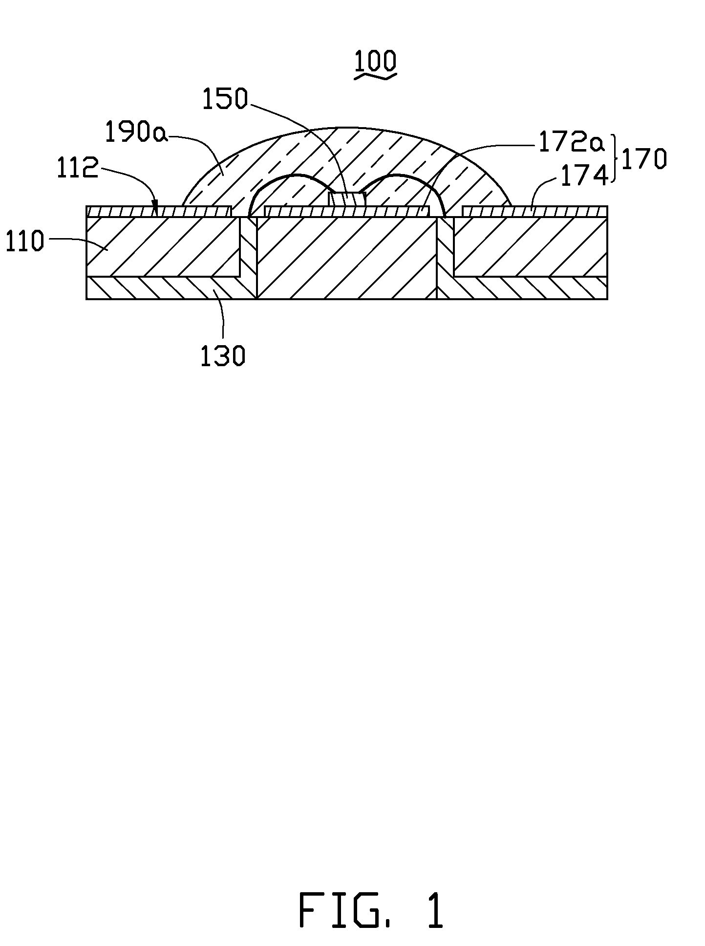
[0015]Referring to FIG. 1, an LED 100 according to a first embodiment is shown. The LED 100 includes a silicon substrate 110, an LED chip 150, and a light pervious encapsulation 190a.

[0016]The silicon substrate 110 is configured for supporting the LED chip 150 and the encapsulation 190a thereon, and for dissipating heat generated from the LED chip 150. The silicon substrate 110 includes a surface 112. The surface 112 can be a flat surface.

[0017]A plurality of electrodes 130 extends through the silicon substrate 110 and is made of an electrically conductive material. The electrically conductive material can be an electrically conductive paste or a metal, such as gold, silver, aluminum and so on. In the present embodiment, each of the electrodes 130 has an L shaped cross section.

[0018]The LED chip 150 is mounted on the surface 12 of the silicon substrat...


PUM


Abstract

An LED includes a substrate having a substantially flat substrate surface, a plurality of electrodes extending through the substrate, an LED chip configured for emitting light, a first and a second coplanar reflective layers formed on the surface, and a light pervious encapsulation member mounted on the substrate surface. The light pervious encapsulation member covers the LED chip and the first reflective layer and a portion of the second reflective layer. The LED chip is mounted on the substrate surface and electrically connected with the electrodes. The first reflective layer and the second reflective layer are configured for reflecting the light emitted from the LED chip.

Description

CROSS REFERENCE TO RELATED APPLICATION[0001]This application is related to commonly-assigned application Ser. No. 12 / 168,783, entitled “LIGHT EMITTING DIODE WITH AUXILIARY ELECTRIC COMPONENT”. Disclosures of the above-identified application are incorporated herein by reference.BACKGROUND[0002]1. Field of the Invention[0003]The present invention relates generally to light-emitting devices and more particularly to a light-emitting diode (LED).[0004]2. Description of Related Art[0005]Generally, an LED includes a substrate, an LED chip disposed on the substrate, and a light pervious encapsulation covering the LED chip. When the LED chip emits light, the light eventually passes through the light pervious encapsulation. Usually, a bowl or cup shaped space is defined in the substrate for receiving the LED chip. An intensity distribution of the LED can be adjusted according to the design of the bowl or cup shaped space. However, light emitted from the LED chip may be internally reflected ma...

Claims


Application Information

Patent Timeline
Patent Type & Authority Patents(United States)
IPC IPC(8): H01L33/00H01L33/54H01L33/60
CPCH01L31/14H01L33/60H01L33/54H01L2924/1815H01L2924/0002H01L2224/48091H01L2924/00014H01L2924/00
Inventor WANG, CHUN-WEIHSU, HUNG-KUANGJIANG, WEN-JANG
Owner FOXSEMICON INTEGRATED TECH INC
Why Eureka
Try Eureka