Repositionable base structure for a container

a container and base technology, applied in the field of container base structure, can solve the problems of partial vacuum in the container, container leaning or becoming unstable, container deformation and/or collapse, etc., and achieve the effect of reducing the internal pressure of the container

Active Publication Date: 2007-04-19
CO2 PAC
View PDF42 Cites 181 Cited by
  • Summary
  • Abstract
  • Description
  • Claims
  • Application Information

AI Technical Summary

Benefits of technology

[0012] A method of compensating for vacuum pressure changes within a container including hot filling the container with a product, sealing the container with a closure, cooling the hot filled container, repositioning a base wall adjoining a hi...

Problems solved by technology

As the container and its contents cool, the contents tend to contract and this volumetric change creates a partial vacuum within the container.
In the absence of some means for accommodating these internal volumetric and barometric changes, containers tend to deform and/or collapse.
In addition to these changes that adversely affect the appearance of the container, distortion or deformation can cause the contai...

Method used


Image

  • Repositionable base structure for a container
  • Repositionable base structure for a container
  • Repositionable base structure for a container

Examples


Embodiment Construction

[0018] Embodiments of the invention are discussed in detail below. In describing embodiments, specific terminology is employed for the sake of clarity. However, the invention is not intended to be limited to the specific terminology so selected. While specific exemplary embodiments are discussed, it should be understood that this is done for illustration purposes only. A person skilled in the relevant art will recognize that other components and configurations can be used without parting from the spirit and scope of the invention.

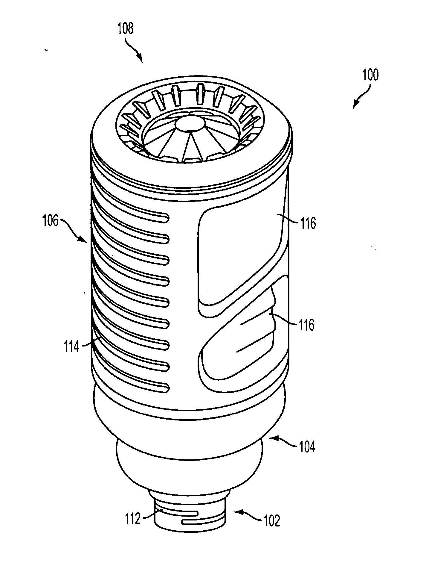
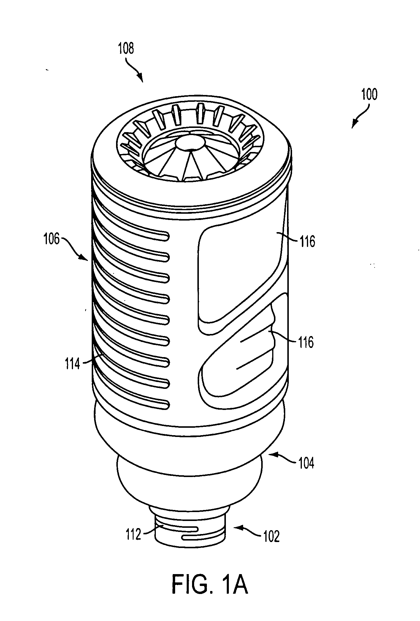
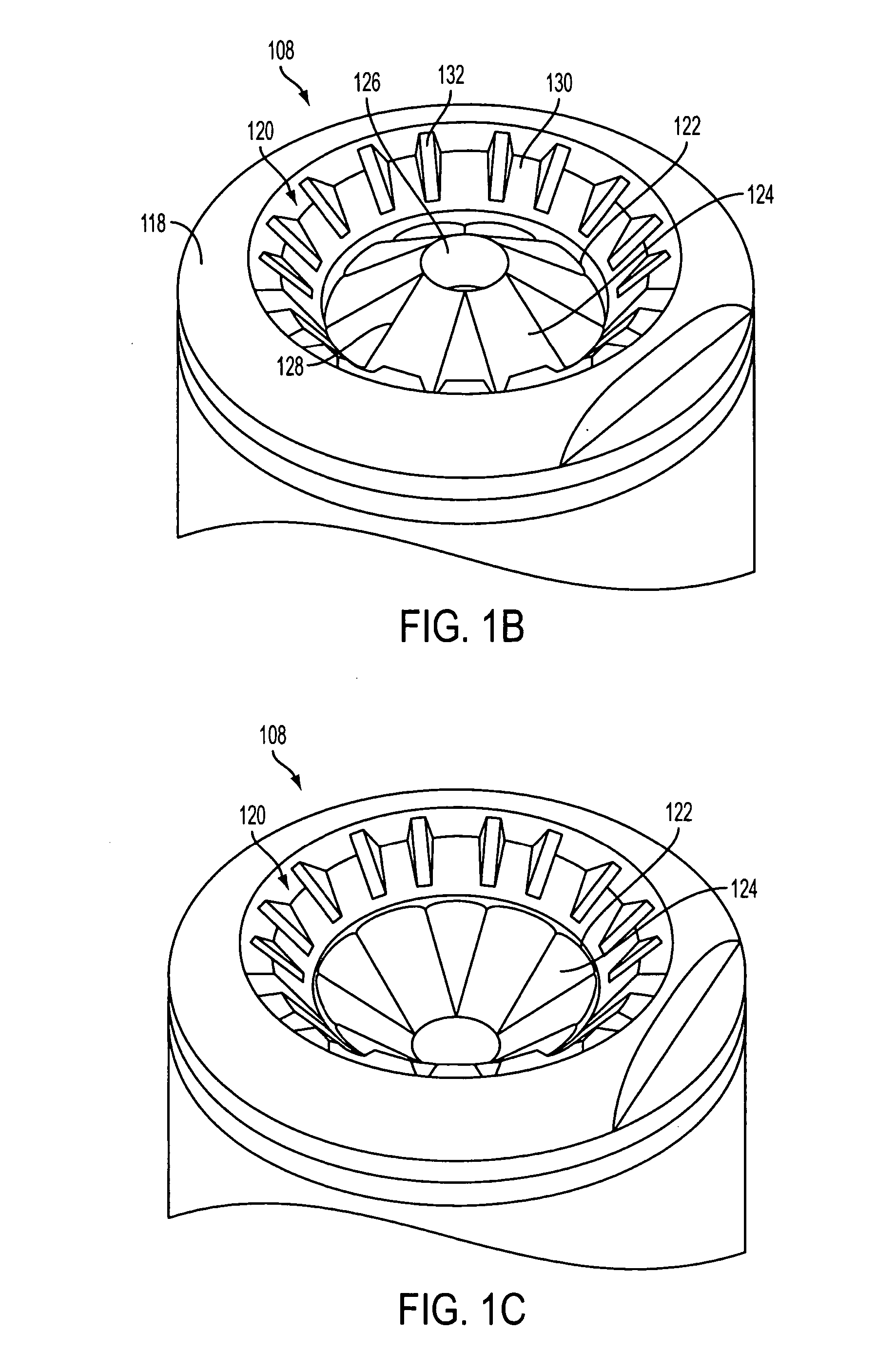
[0019] The present invention generally relates to a base structure of a container that can be repositioned about a hinge to partially reduce an internal vacuum pressure within the container caused by cooling of a product after a hot fill process. FIGS. 1A-1C illustrate an exemplary embodiment of a container 100 having a base structure according to the present invention. Initially, the invention will be described referring to FIGS. 1A-1C.

[0020] According t...


PUM

PropertyMeasurementUnit
Forceaaaaaaaaaa
Pressureaaaaaaaaaa
Angleaaaaaaaaaa

Abstract

A base of a container including a bearing surface, a hinge, a first wall, and a second wall. The first wall sloping in a first direction from the bearing surface to the hinge, and the second wall sloping in a second direction away from the hinge. The second wall is adapted to be repositioned about the hinge with substantially no movement of the first wall.

Description

BACKGROUND OF THE INVENTION [0001] 1. Field of the Invention [0002] The present invention generally relates to a structure of a container base, and more particularly to a base of a container that is repositionable about a hinge in order to partially reduce vacuum pressure experienced by a container during a hot-fill process. [0003] 2. Related Art [0004] Conventionally, manufacturers use a hot-fill process to add a product to a container at an elevated temperature, about 82° C., which can be near the glass transition temperature of the plastic material in the plastic container, and then cap the container. As the container and its contents cool, the contents tend to contract and this volumetric change creates a partial vacuum within the container. In the absence of some means for accommodating these internal volumetric and barometric changes, containers tend to deform and / or collapse. For example, a round container can undergo ovalization, or tend to distort and become out of round. C...

Claims


Application Information

Patent Timeline
IPC IPC(8): B65D90/02B65D85/28
CPCB65D1/0276B65D79/005B29C49/541B65D1/0284B67C2003/226B65D79/0084
Inventor BYSICK, SCOTTTRUDE, GREGORY A.
Owner CO2 PAC
Why Eureka
Try Eureka