
Container for dispensing a substance

Inactive Publication Date: 2012-09-27
MDS GLOBAL HLDG
View PDF9 Cites 44 Cited by
  • Summary
  • Abstract
  • Description
  • Claims
  • Application Information

AI Technical Summary

Benefits of technology

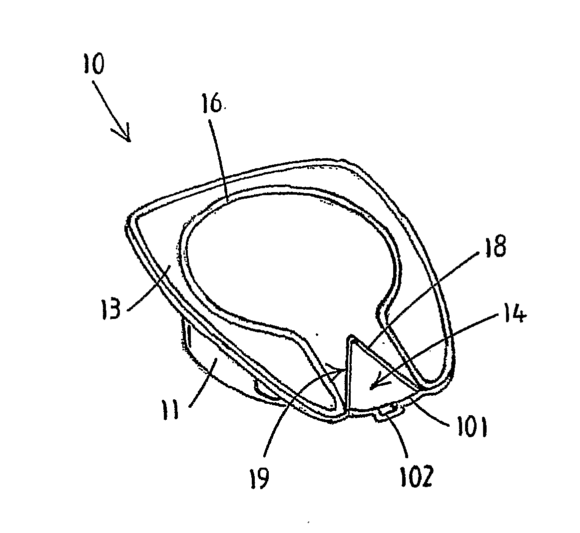
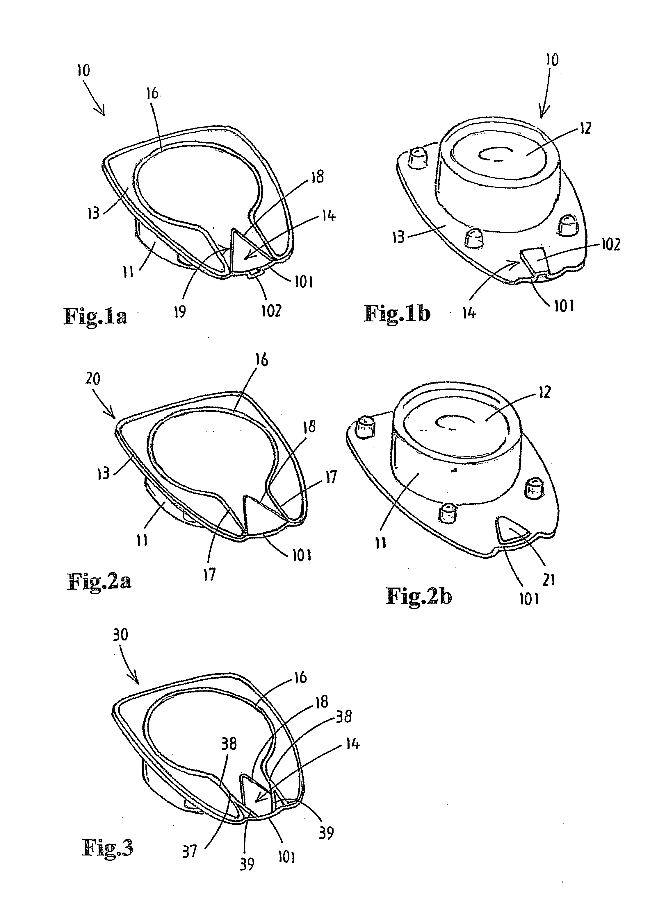
[0011]The second aspect of the invention proposes to provide an indent in the dispensing passage in the upper surface of the dispensing part, but at a distance from the dispensing edge of the dispensing part. This indent provides the possibility to press on the covering foil at the location of the indent whereby the foil is pressed into the indent. This will stress the foil and will rupture any inadvertent seal formed between the dispensing edge of the dispensing part and the foil caused by the cutting tool. This pressing of the covering foil can be done during production, but it is also possible to provide the dispensing apparatus with a member, which will press the foil automatically when the container is placed in the dispensing apparatus.
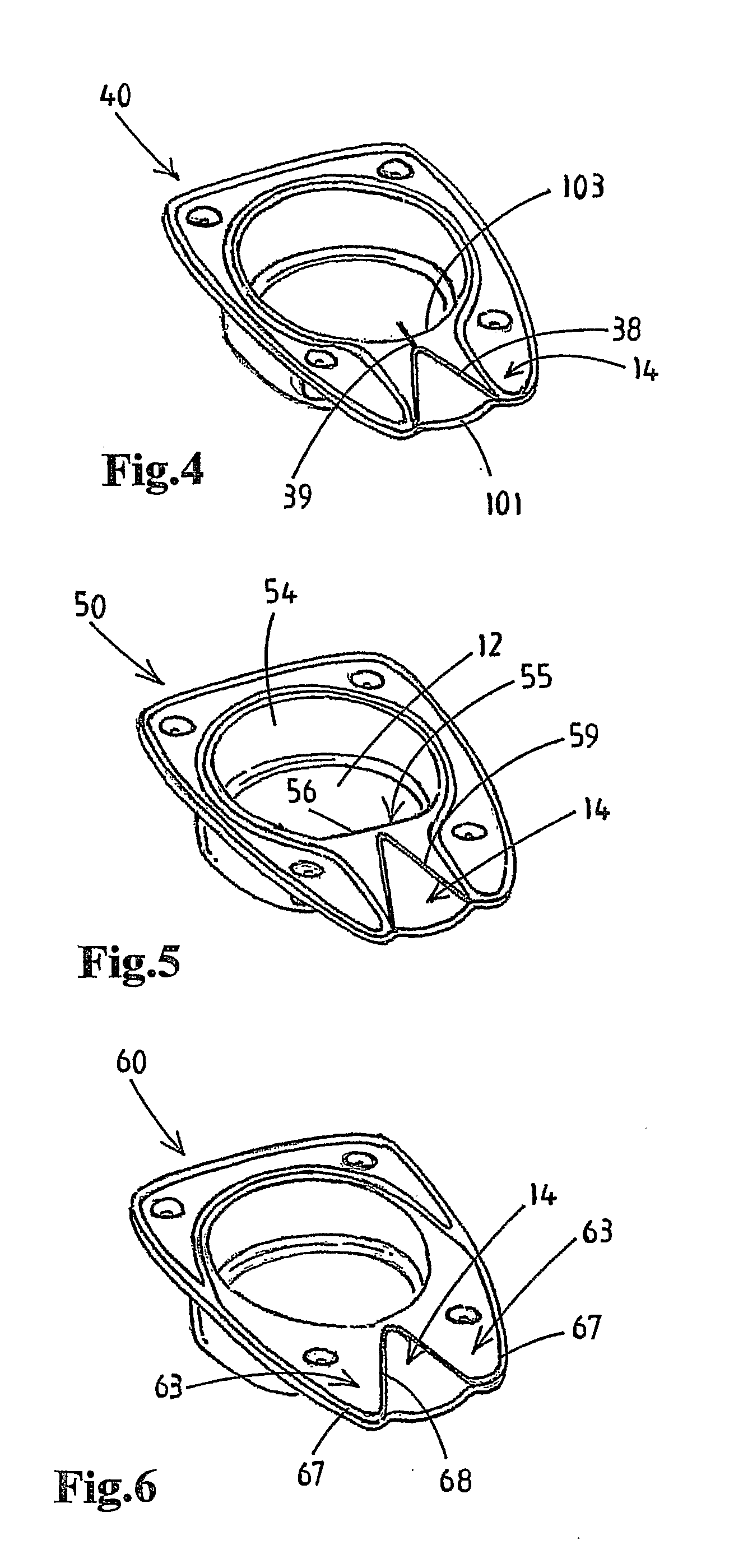
[0013]The outlet seams that according to this third aspect converge force the substance to flow through a smaller opening at the dispensing edge. This prevents that a shower of different flows or jets is exiting from the dispensing edge. Thereby spoiling of the dispensing apparatus is prevented.
[0017]According to the fifth aspect, a flat wall portion is provided in the filling cavity on the side where the dispensing part is provided. This results in a straight edge between the filling cavity and the dispensing part. With fixed outer dimensions of the circumferential rim including the dispensing part (due to the existing dispensing apparatus having a certain dimension for receiving the circumferential rim), said straight edge provides a longer dispensing part. This allows the passage to be longer and thus the rupturable sealing seam, which is mostly in a V-shape, to be more elongate in shape. Thereby, more cover sheet material is “free” to bulge out around it, and the rupturing will initiate more easily in the point of the V-shape. Furthermore a rupturable seal extending over a longer length portion of the outlet passage provides an easier, more gradual opening of the weak seal, with the substance under less pressure, whereby splashing of the substance upon opening the container is mitigated.
[0019]The sixth aspect of the invention provides a sealing seam sealing the covering sheet to the dispensing part, which sealing seam has a general W-shape. The central portion of the “W” is constituted by the rupturable sealing seam, which has the shape of an inverted “V”. The advantage of this sealing seam configuration is that there is overall a greater distance between the rupturable sealing seam and the strong sealing seams on the dispensing part, whereby a greater portion of the covering sheet is allowed to bulge out. Thereby the rupturable seal will open under a lower internal pressure in the container and a more gradual opening results. A more gradual rupturing under a lower pressure of the rupturable sealing seam results in a reduction elimination of the splashing of the outgoing flow of substance.
[0022]The seventh aspect of the invention provides the feature that at the dispensing edge the layers of material are not overlying, whereby it is prevented that during cutting of the circumferential rims during production, the covering foil is pressed by the cutting tool in the top surface of the dispensing part to such an extent that an inadvertent sealing takes place at the dispensing edge.
[0024]However it is not in all cases necessary to have a weakened sealing seam. In some applications all sealing seams attaching the cover sheet to the circumferential rim may be of the same strength and it is sufficient that the rupturable sealing seam is surrounded by a sufficient area of cover sheet material, preferably cover foil, that is allowed to bulge out. In other words, in some occasions it is sufficient that the point where the rupturing should initiate is spaced sufficiently from the other sealing seams. The specific geometry of the sealing seams in this case provides for the effect that the sealing seams upon pressurizing the content of the container will brake at the rupturable sealing seam.

Problems solved by technology

This will stress the foil and will rupture any inadvertent seal formed between the dispensing edge of the dispensing part and the foil caused by the cutting tool.

Method used


Image

  • Container for dispensing a substance
  • Container for dispensing a substance
  • Container for dispensing a substance

Examples


Embodiment Construction

[0053]In the following containers according to several aspects of the invention are shown. Each of these containers have in common that they contain a substance, e.g. syrup for a soft drink or a concentrate for coffee or other beverages. The substance is dispensed by a dispensing apparatus directly from the container into a serving container, e.g. a glass, a cup, or a bottle. Also water is dispensed by the dispensing apparatus into the serving container such that mixing of the substance and the water takes place in the serving container. The containers with substance are adapted to be placed dispensing apparatus, which comprises compressing means for compressing the container bodies so as to expel the substance from the container.

[0054]In FIG. 1a and FIG. 1b a container 10 containing a substance is shown. The container 10 has a generally cup shaped container body 11, preferably made of plastic sheet material or another suitable material. The cup shaped body 11 defines at its inner s...


PUM


Abstract

A container containing a substance includes a preformed deformable body defining a filling cavity. The container body has an opening and an integral planar circumferential rim surrounding the opening, which opening is closed by a cover sheet which is sealed to the circumferential rim by means of a circumferential sealing seam. The circumferential rim has a dispensing part which is covered by the cover sheet. The cover sheet is sealed to an upper surface of the dispensing part by at least one rupturable sealing seam and outlet seams defining an outlet passage from the rupturable sealing seam towards the edge of the dispensing part of the circumferential rim, such that, when the rupturable sealing seam is broken, the substance is allowed to flow through the outlet passage between the surface of the dispensing part and the cover sheet towards the edge of the dispensing part.

Description

CROSS-REFERENCE TO RELATED APPLICATIONS[0001]This application is the National Stage of International Application No. PCT / NL2009 / 000218, filed Nov. 12, 2009, the contents of which is incorporated by reference herein.FIELD OF THE INVENTION[0002]The present invention relates to dispensing a substance from a container by means of a dispensing apparatus.BACKGROUND OF THE INVENTION[0003]The present invention proposes to dispense a substance from a container filled with a single portion of substance. In particular the substance may be a concentrate, like e.g. a syrup for preparation of a beverage. The container comprises a preformed deformable body, preferably made of sheet material, defining a filling cavity, which body has an opening and an integral planar circumferential rim at least partly surrounding said opening. The opening is closed by a cover sheet which is sealed to the planar circumferential rim by means of a sealing seam.[0004]According to the invention the substance, e.g. syru...

Claims


Application Information

Patent Timeline
IPC IPC(8): B65D17/32B67B7/00
CPCB65D77/2036B65D2577/2066B65D83/0094B65D77/20B65D77/2028B65D77/204B65D77/206B65D77/38B65D83/00
Inventor SCHOLVINCK, MICHIEL OLIVIERWILLEMSEN, ROBERTHEKKENBERG, SEBASTIAAN WILLEMVAN OIRSCHOT, ROELAND PETRUS MARIASTERNGOLD, EDOUARD
Owner MDS GLOBAL HLDG
Learn More