

Optical lens system
a technology of optical lens and lens element, applied in the field of optical lens system, can solve the problems of insufficient high-end imaging module of conventional lens system comprising four lens elements, electronic products becoming more and more powerful, etc., and achieve the effect of reducing the size of the optical lens system, reducing the sensitivity of the optical system, and improving image resolution
- Summary
- Abstract
- Description
- Claims
- Application Information
AI Technical Summary
Benefits of technology
Problems solved by technology
Method used
Image

Examples
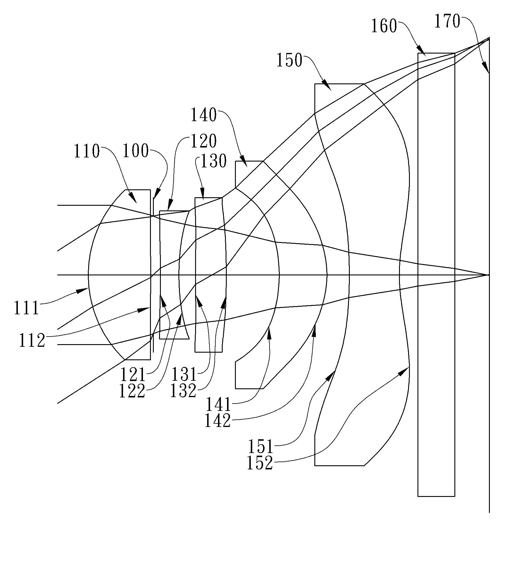
first embodiment
[0082]In the present optical lens system, the focal length of the optical lens system is f, and it satisfies the relation: f=5.97 (mm).
[0083]In the first embodiment of the present optical lens system, the f-number of the optical lens system is Fno, and it satisfies the relation: Fno=2.60.
[0084]In the first embodiment of the present optical lens system, half of the maximum field of view of the optical lens system is HFOV, and it satisfies the relation: HFOV=32.9 (degrees).
[0085]In the first embodiment of the present optical lens system, the Abbe number of the first lens element 110 is V1, the Abbe number of the second lens element 120 is V2, and they satisfy the relation: V1−V2=34.5.
[0086]In the first embodiment of the present optical lens system, the Abbe number of the second lens element 120 is V2, the Abbe number of the third lens element 130 is V3, and they satisfy the relation: |V2−V3|=2.46.
[0087]In the first embodiment of the present optical lens system, the thickness of the se...
second embodiment
[0100]In the present optical lens system, the focal length of the optical lens system is f, and it satisfies the relation: f=4.18 (mm).
[0101]In the second embodiment of the present optical lens system, the f-number of the optical lens system is Fno, and it satisfies the relation: Fno=2.85.
[0102]In the second embodiment of the present optical lens system, half of the maximum field of view of the optical lens system is HFOV, and it satisfies the relation: HFOV=30.4 (degrees).
[0103]In the second embodiment of the present optical lens system, the Abbe number of the first lens element 210 is V1, the Abbe number of the second lens element 220 is V2, and they satisfy the relation: V1−V2=32.0.
[0104]In the second embodiment of the present optical lens system, the Abbe number of the second lens element 220 is V2, the Abbe number of the third lens element 230 is V3, and they satisfy the relation: |V2−V3|=0.00.
[0105]In the second embodiment of the present optical lens system, the thickness of t...
third embodiment
[0118]In the present optical lens system, the focal length of the optical lens system is f, and it satisfies the relation: f=5.96 (mm).
[0119]In the third embodiment of the present optical lens system, the f-number of the optical lens system is Fno, and it satisfies the relation: Fno=2.66.
[0120]In the third embodiment of the present optical lens system, half of the maximum field of view of the optical lens system is HFOV, and it satisfies the relation: HFOV=32.5 (degrees).
[0121]In the third embodiment of the present optical lens system, the Abbe number of the first lens element 310 is V1, the Abbe number of the second lens element 320 is V2, and they satisfy the relation: V1−V2=32.5.
[0122]In the third embodiment of the present optical lens system, the Abbe number of the second lens element 320 is V2, the Abbe number of the third lens element 330 is V3, and they satisfy the relation: |V2−V31=0.00.
[0123]In the third embodiment of the present optical lens system, the thickness of the se...
PUM
 Abstract
Description
Claims
Application Information