
Minimizing estimation time for rake fingers with help of a speed sensor

Inactive Publication Date: 2008-02-14
SONY ERICSSON MOBILE COMM AB
View PDF9 Cites 6 Cited by
  • Summary
  • Abstract
  • Description
  • Claims
  • Application Information

AI Technical Summary

Benefits of technology

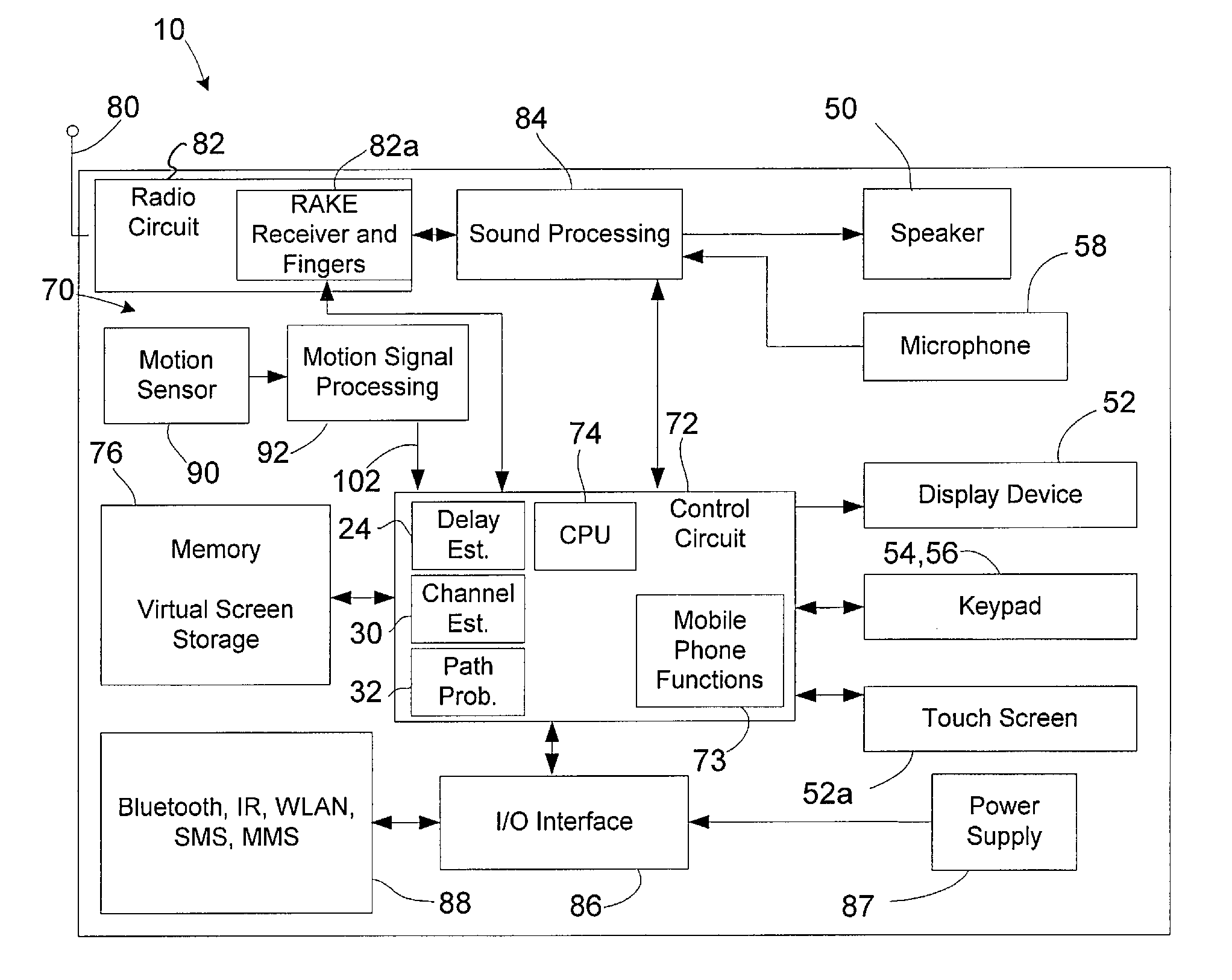
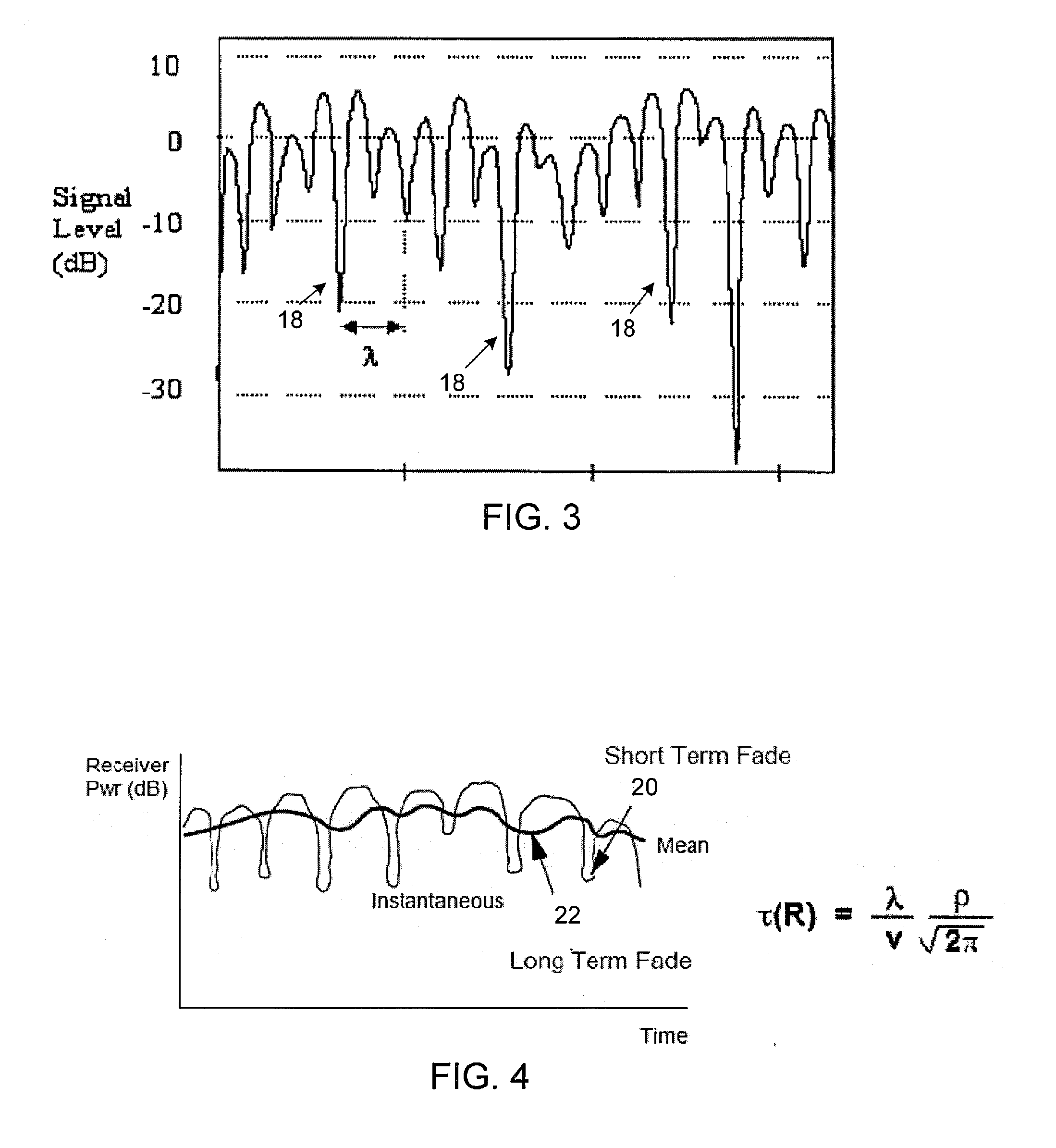
[0008]The present invention minimizes the estimation time for RAKE fingers by determining velocity of a user station. This can be accomplished, for example, by including a sensor in the user station that enables the determination of user station's velocity. The sensor may be a velocity sensor, an accelerometer, or any other sensor that enables a velocity of the user station to be determined. Alternatively, velocity may be determined by tracking a change in location of the user station (e.g., via GPS tracking or the like). The velocity of the user station is utilized in a calculation of the average duration of a fade, and this information then is used to set the RAKE fingers. As a result, searching is not performed by the RAKE fingers in areas where nulls are significant relative to signal levels.
[0011]According to another aspect of the invention, the time delay of the at least one finger can be set such that the at least one finger avoids searching in areas of the signal where fading nulls are present that have a magnitude greater than a predefined level.
[0023]According to another aspect of the invention, a method of minimizing estimation time for at least one finger of a RAKE receiver in electronic equipment includes: determining a velocity of the electronic equipment; using the velocity to determine a duration between fading nulls of a signal receivable by the RAKE receiver; and setting a time delay of the at least one finger based on the duration between fading nulls.
[0030]According to another aspect of the invention, a computer program embodied on a computer readable medium and operable in electronic equipment for minimizing estimation time for at least one finger of a RAKE receiver in the electronic equipment, includes: code that determines a velocity of the electronic equipment; code that uses the velocity to determine a duration between fading nulls of a signal receivable by the RAKE receiver; and code that sets a time delay of the at least one finger based on the duration between fading nulls.

Problems solved by technology

However, in mobile telecommunications the channels may be subject to additional fading due to the motion of the receiver.
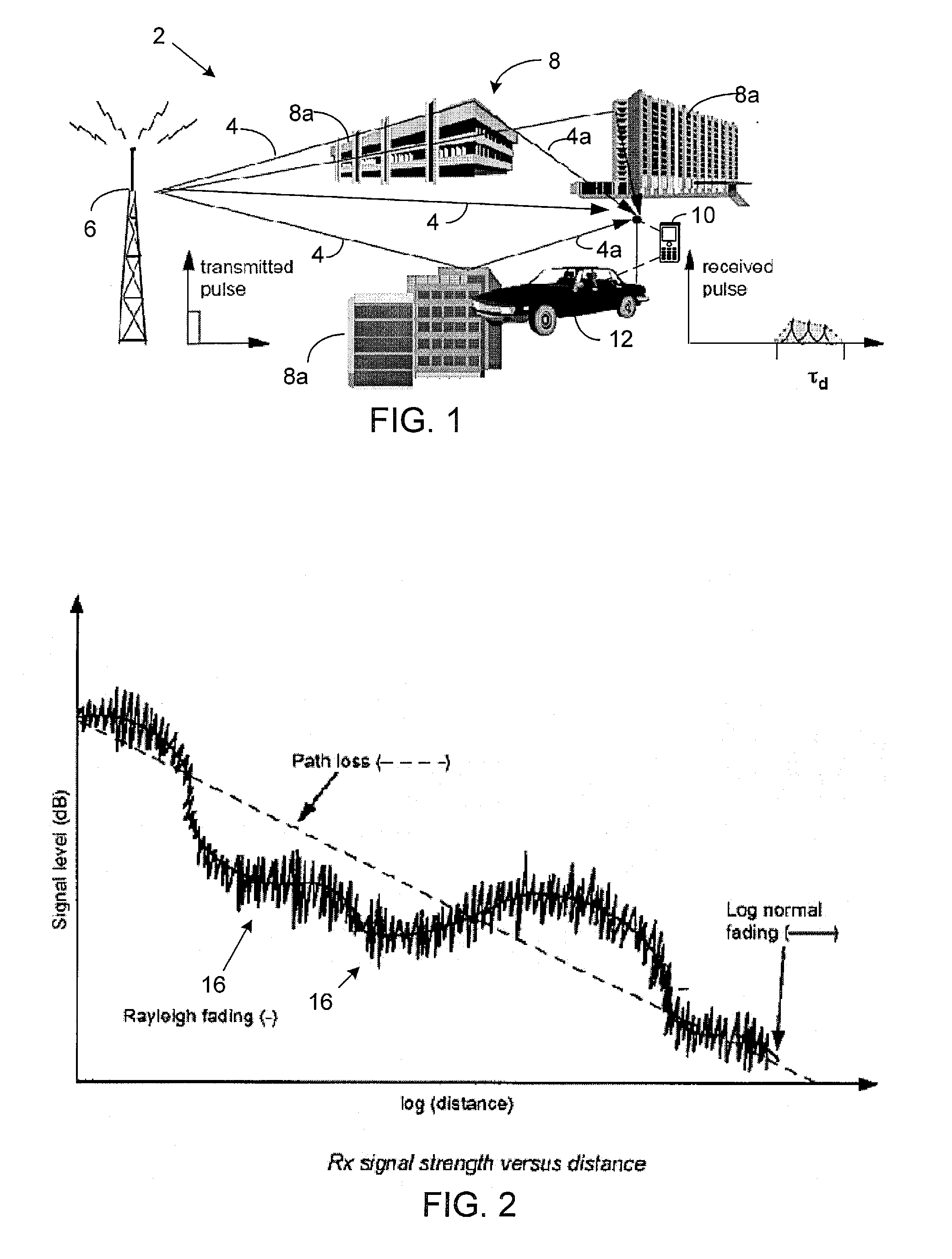
One problem encountered in setting the RAKE fingers is the impact of Raleigh fading, which can cause strong nulls in the received signal.
When severe Rayleigh fading is present, the replica signals detected by the fingers may not be discernable, or the process of searching these signals may take significant time, resulting in performance degradation of the communication system.
As a result, searching is not performed by the RAKE fingers in areas where nulls are significant relative to signal levels.

Method used


Image

  • Minimizing estimation time for rake fingers with help of a speed sensor
  • Minimizing estimation time for rake fingers with help of a speed sensor
  • Minimizing estimation time for rake fingers with help of a speed sensor

Examples


Embodiment Construction

[0045]The present invention will now be described with reference to the drawings, wherein like reference numerals are used to refer to like elements throughout.

[0046]The term “electronic equipment” includes portable radio communication equipment. The term “portable radio communication equipment,” which herein after is referred to as a “mobile radio terminal,”“mobile phone,”“mobile device,” or “mobile terminal”, and the like, includes all equipment such as mobile telephones, pagers, communicators, i.e., electronic organizers, personal digital assistants (PDAs), smartphones, portable communication apparatus or the like.

[0047]In the present application, the invention is described primarily in the context of a mobile phone. However, it will be appreciated that the invention is not intended to be limited to a mobile phone and can be any type of electronic equipment.

[0048]In a wireless mobile communication system, a signal can travel from transmitter to receiver over multiple reflective p...


PUM


Abstract

An electronic equipment includes a RAKE receiver that includes at least one finger having a settable delay, a transducer operable to provide a signal indicative of motion of the electronic equipment, and a delay estimator circuit operative to calculate a duration between fading nulls of a received signal based on the motion signal of the electronic equipment. The time delay of the at least one finger is set based on the duration between fading nulls.

Description

TECHNICAL FIELD OF THE INVENTION[0001]The present invention relates generally to electronic equipment and, more particularly, to a system and method for minimizing the estimation time for RAKE fingers of a RAKE receiver.DESCRIPTION OF THE RELATED ART[0002]Wireless communications have become prevalent in business, personal, and other applications, and as a result the technology for such communications continues to advance in various areas. One such advancement includes the use of spread spectrum communications, including that of code division multiple access (“CDMA”). In such communications, a user station (e.g., a hand held cellular phone) communicates with a base station, where typically the base station corresponds to a “cell”. CDMA systems are characterized by simultaneous transmission of different data signals over a common channel by assigning each signal a unique code.[0003]CDMA includes various different operating modes and standards such as a 1xRTT mode sometimes referred to...

Claims


Application Information

Patent Timeline
IPC IPC(8): H04B1/00
CPCH04B1/7117H04B1/7115
Inventor TUDOSOIU, BOGDAN
Owner SONY ERICSSON MOBILE COMM AB
Learn More