
Cup assembly structure

a technology of assembly structure and cup, applied in the direction of packaging, sealing, containers preventing decay, etc., can solve the problems of manufacturing inconvenience and waste of cost, and achieve the effect of different visual effects

Inactive Publication Date: 2008-02-21
CHEN WEN KUEI
View PDF10 Cites 3 Cited by
  • Summary
  • Abstract
  • Description
  • Claims
  • Application Information

AI Technical Summary

Benefits of technology

[0006]The primary object of present invention is to provide a cup assembly structure wherein a picture can be fixed and assembled on an exterior of cup body with a fixing device or an overlay, and can be exchanged freely, such that a different visual effect can be generated for the entire cup.

Problems solved by technology

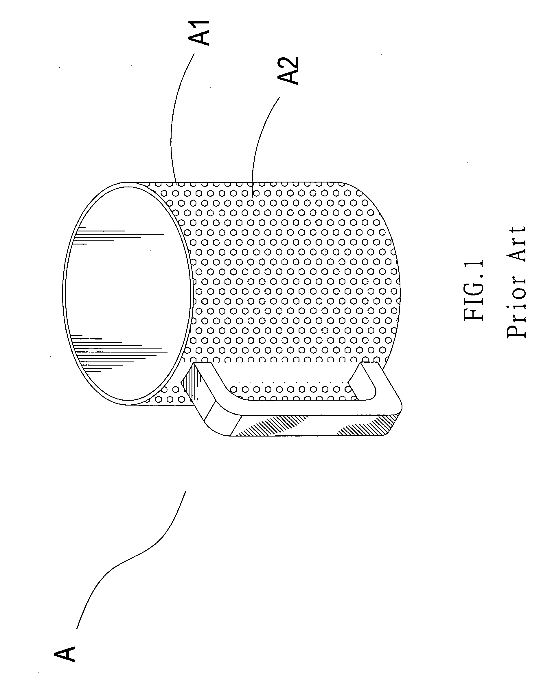
If the pattern A2 needs to be changed, then the required pattern A2 should be painted or printed on an exterior of the cup body A1 in producing the cup body A1, which will cause a waste of cost and an inconvenience in manufacturing.

Method used


Image

  • Cup assembly structure
  • Cup assembly structure
  • Cup assembly structure

Examples


Embodiment Construction

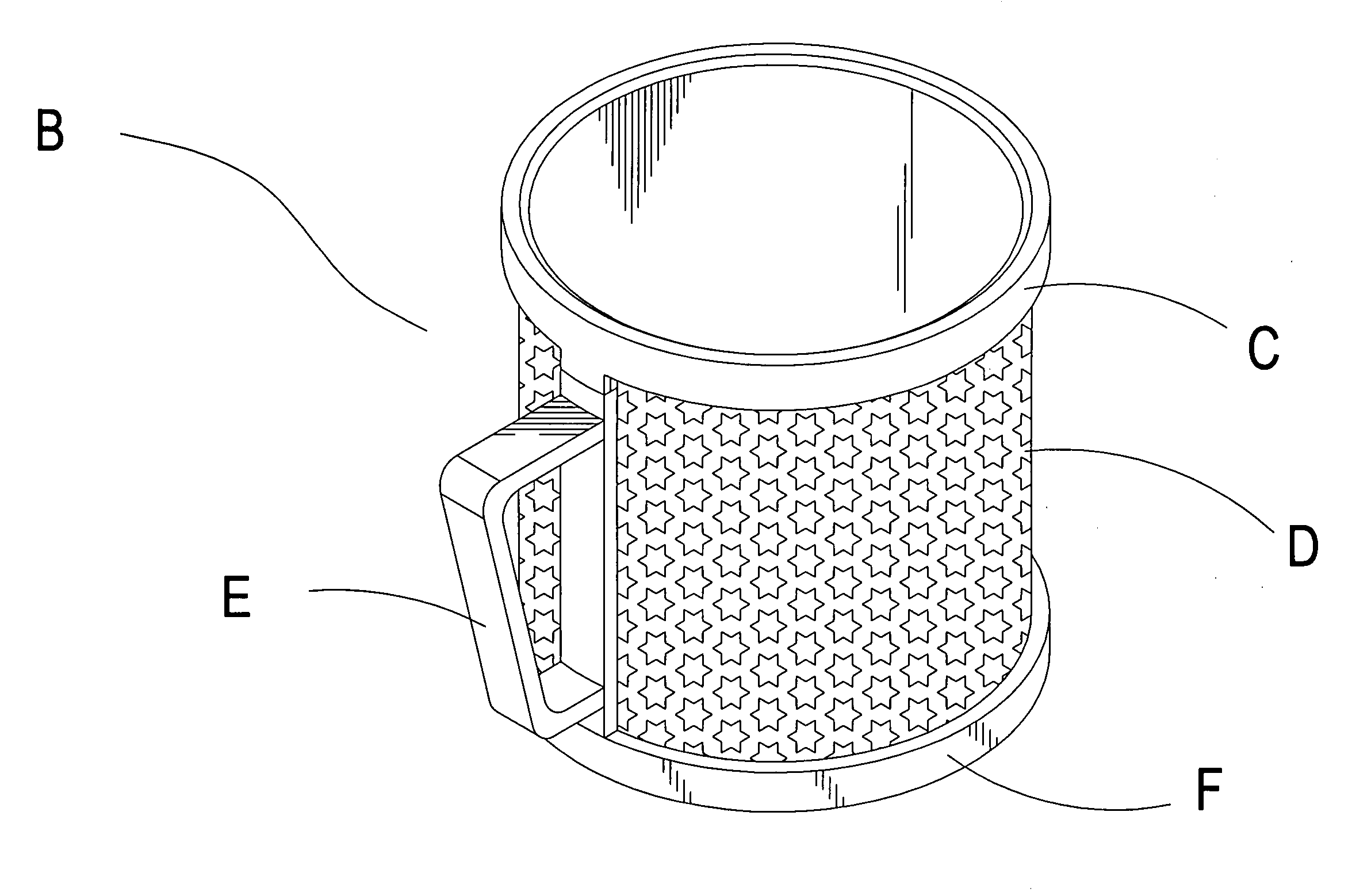
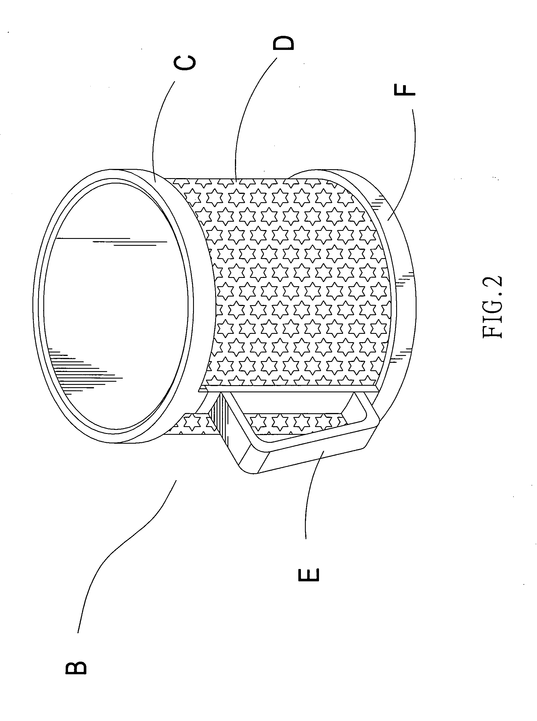
[0017]Referring to FIG. 2 and FIG. 3, the present invention is to provide a cup assembly structure, wherein a cup B is constituted by a body C, a panel D, a fixing device E, and a snap ring F. An exterior of the body C is provided with the panel D, an exterior of a side of the body C and panel D is connected with the fixing device E, and an end at an exterior of the body C is connected with the snap ring F.

[0018]An interior of the body C is provided with an emplacement chamber C1, and an exterior of the body C is provided with a plurality of projection members C2, a latching piece C3, a groove C4, and a plurality of slideways C5. The plural projection members C2 are fitted and fixed with a plurality of holes D1 located on the panel D, and a plurality of concaved holes E2 on the fixing device E, the latching piece C3 provides a latching and fixing for an extension end E1 at one side of the fixing device E, the groove C4 provides an affixation and connection for a bending end E3 locat...


PUM


Abstract

A cup assembly structure includes a cup which is composed of a body, a panel, a fixing device, and a snap ring. Through a plurality of projection members, a latching piece, and a groove on the body to be fitted and connected with a plurality of concaved holes, an extension end, and a bending end located on the fixing device, and then through a plurality of protrusions on the snap ring to be fixed with a plurality of slideways of the body, the panel which is located at an exterior of the body can be firmly assembled, and the panel of different pattern can be exchanged, so as to increase a visual effect of using the cup.

Description

BACKGROUND OF THE INVENTION[0001](a) Field of the Invention[0002]The present invention relates to a cup assembly structure, and more particularly to a cup assembly structure wherein a picture can be fixed and assembled on an exterior of cup body with a fixing device or an overlay.[0003](b) Description of the Prior Art[0004]Referring to FIG. 1, for a conventional cup A, a pattern A2 at an exterior of a cup body A1 is formed by colored painting or printing in producing the cup body A1; therefore, it is not able to exchange the pattern A2 hereafter. If the pattern A2 needs to be changed, then the required pattern A2 should be painted or printed on an exterior of the cup body A1 in producing the cup body A1, which will cause a waste of cost and an inconvenience in manufacturing.[0005]Accordingly, how to eliminate the aforementioned shortcomings is a technical issue to be solved by the inventor of present invention.SUMMARY OF THE INVENTION[0006]The primary object of present invention is ...

Claims


Application Information

Patent Timeline
IPC IPC(8): B65D25/10
CPCB65D25/205B65D25/2861B65D25/2814
Inventor CHEN, WEN-KUEI
Owner CHEN WEN KUEI
Learn More