Rotary Impact Mill

a rotary impact mill and hammer mill technology, applied in the field of rotary impact mills, can solve the problems of impact hammer wear, requiring continual maintenance and down time of the hammermill,

Inactive Publication Date: 2008-02-21
NOVATEK IP
View PDF5 Cites 24 Cited by
  • Summary
  • Abstract
  • Description
  • Claims
  • Application Information

AI Technical Summary

Problems solved by technology

Due to the impact and / or abrasive nature of the material, the impact hammers may wear requiring continual maintenance and down time of the hammermill.

Method used


Image

  • Rotary Impact Mill
  • Rotary Impact Mill
  • Rotary Impact Mill

Examples


Embodiment Construction

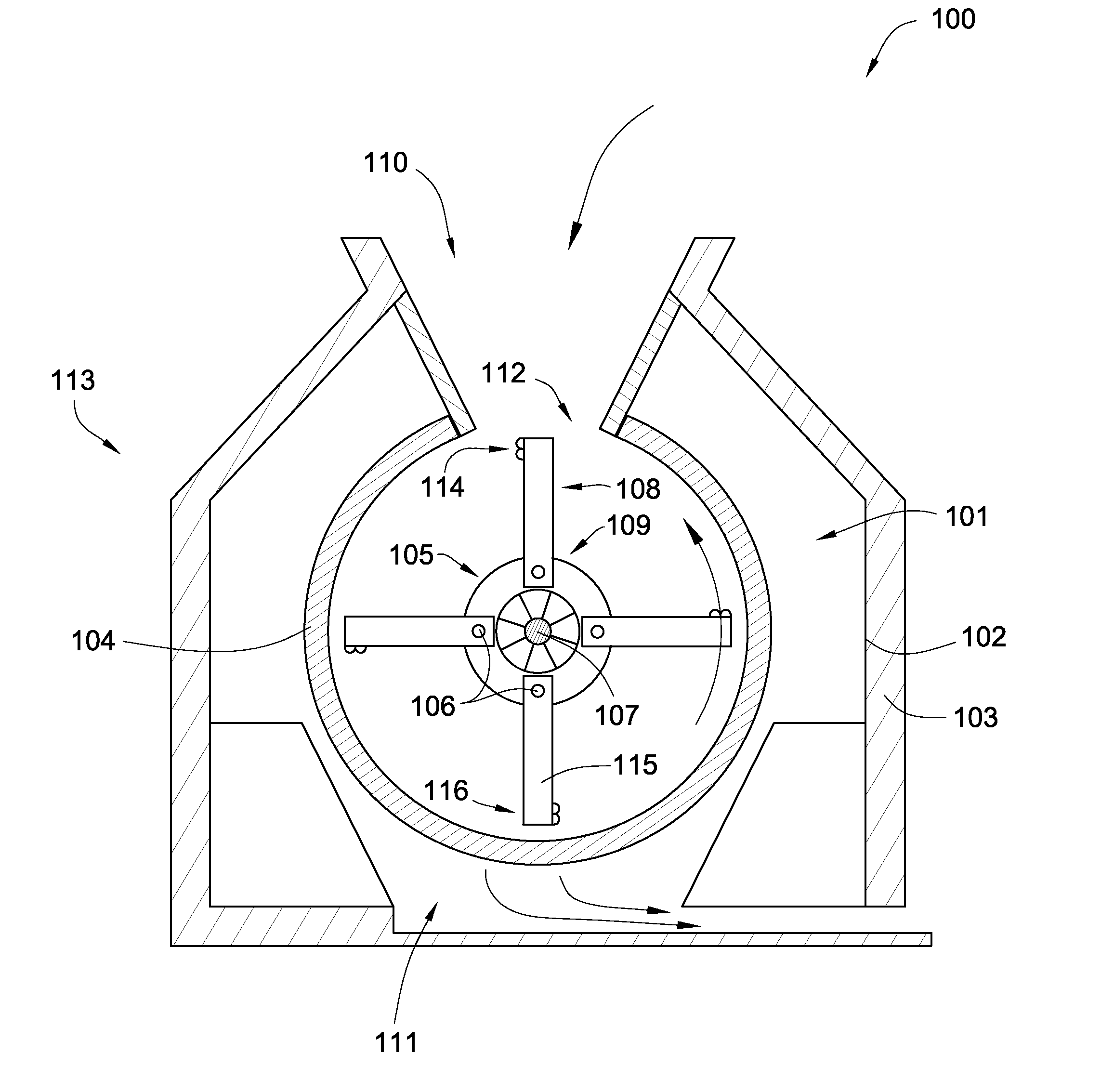
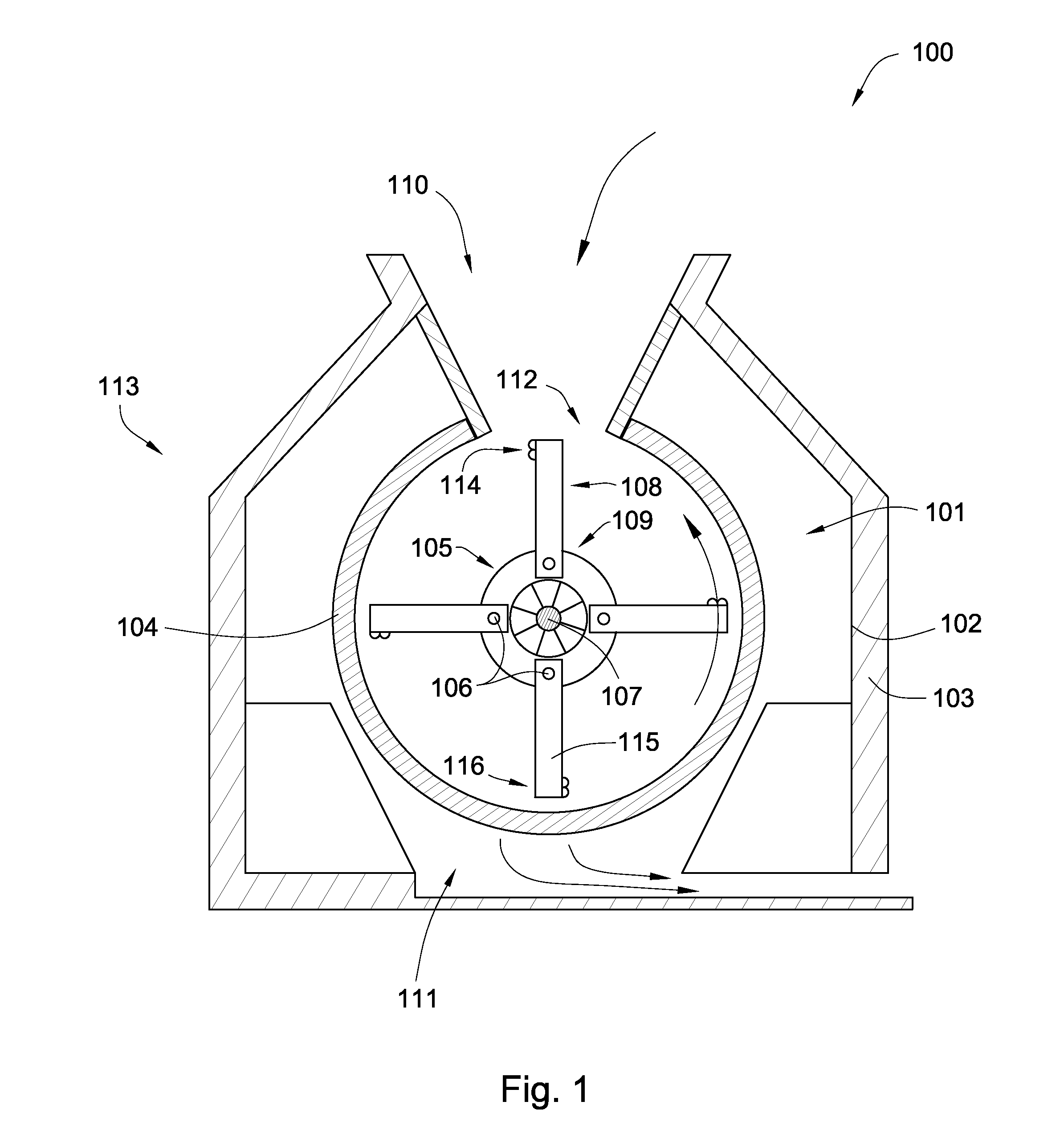
[0033]FIG. 1 is a cross sectional diagram of an embodiment of a rotary impact mill 100. A milling chamber 101 is defined by at least one wall 102 of a housing 103 which may support an internal screen 104, which is typically cylindrical or polygonal. Within the screen 104 a rotary assembly 105 comprises a plurality of shafts 106 connected to a central shaft 107 which is in turn connected to a rotary driving mechanism (not shown). The rotary driving mechanism may be a motor typically used in the art to rotate the rotor assembly of other hammermills. Although there are four shafts 106 shown, one, two, or any desired number of shafts may be used. A plurality of impact hammers 108 are longitudinally spaced and connected to each of the shafts 106 at the hammer's proximal end 109. The hammers 108 may be rigidly attached to the shafts 106 or the hammers 108 may be free-swinging. In some embodiments, the rotor assembly 105 comprises just the central shaft 107 and the impact hammers 108 are c...


PUM


Abstract

In one aspect of the invention, a rotary impact mill has a milling chamber defined by a housing with an inlet, an outlet, and at least one wall. A plurality of impact hammers located within the milling chamber are fastened to and longitudinally disposed along a rotor assembly that is connected to a rotary driving mechanism. At least one of the impact hammers has a plurality of inserts arranged adjacent one another in a row and attached to a body of the hammer, wherein a first end of at least one insert is complementary to a second end of an adjacent insert.

Description

CROSS REFERENCES[0001]This Patent Application is a continuation-in-part of U.S. patent application Ser. No. 11 / 424,833 filed on Jun. 16, 2006 and entitled Rotary Impact Mill, which is herein incorporated by reference in its entirety.BACKGROUND OF THE INVENTION[0002]Hammermills are often used to reduce the size of solid material. Materials often used in hammermills include coal, asphalt, cement, limestone, chemical fertilizer, barks, rocks, minerals, and food products. The materials are often fed into an inlet where the material falls into a milling chamber. The milling chamber typically comprises a plurality of impact hammers and may comprise a screen. The impact hammers are typically fastened at a proximal end to a rotary assembly; they are either rigidly fixed to the rotor assembly or the impact hammers may be free-swinging. As the material is fed into the chamber, the rotary assembly rotates bringing the impact hammers into contact with the material. The size reduction on each im...

Claims


Application Information

Patent Timeline
Patent Type & Authority Applications(United States)
IPC IPC(8): B02C13/09
CPCB02C13/09B02C13/282B02C13/2804B02C13/28
Inventor HALL, DAVID R.DUKE, TIMOTHY
Owner NOVATEK IP
Why Eureka
Try Eureka