Method and System for Decoding and Displaying 3D Light Fields

a technology of light field and decoding method, which is applied in the field of scalable decoding of 3d light field, can solve the problems of disturbing artifacts in the display of light field data, easy aliasing of resampling, etc., and achieves the effect of minimizing such inter-perspective aliasing and high quality rendering

Inactive Publication Date: 2008-02-21
MITSUBISHI ELECTRIC RES LAB INC
View PDF0 Cites 271 Cited by
  • Summary
  • Abstract
  • Description
  • Claims
  • Application Information

AI Technical Summary

Benefits of technology

[0014]The invention provides a method for resampling light fields that minimizes such inter-perspective aliasing. The method provides a high-quality rendering of the light field onto automultiscopic display devices. The method combines a light field reconstruction filter and a display prefilter that is determined according to a sampling grid of the display device.
[0015]In contrast with prior art methods, the present resampling method does not require depth information. The method efficiently combines multiple filtering stages to produce high quality renderings. The method can be used to display light fields onto a lenticular display screen or a parallax-barrier display screen.

Problems solved by technology

However, resampling is prone to aliasing artifacts.
The most disturbing artifacts in the display of light field data are caused by inter-perspective aliasing.

Method used


Image

  • Method and System for Decoding and Displaying 3D Light Fields
  • Method and System for Decoding and Displaying 3D Light Fields
  • Method and System for Decoding and Displaying 3D Light Fields

Examples


second embodiment

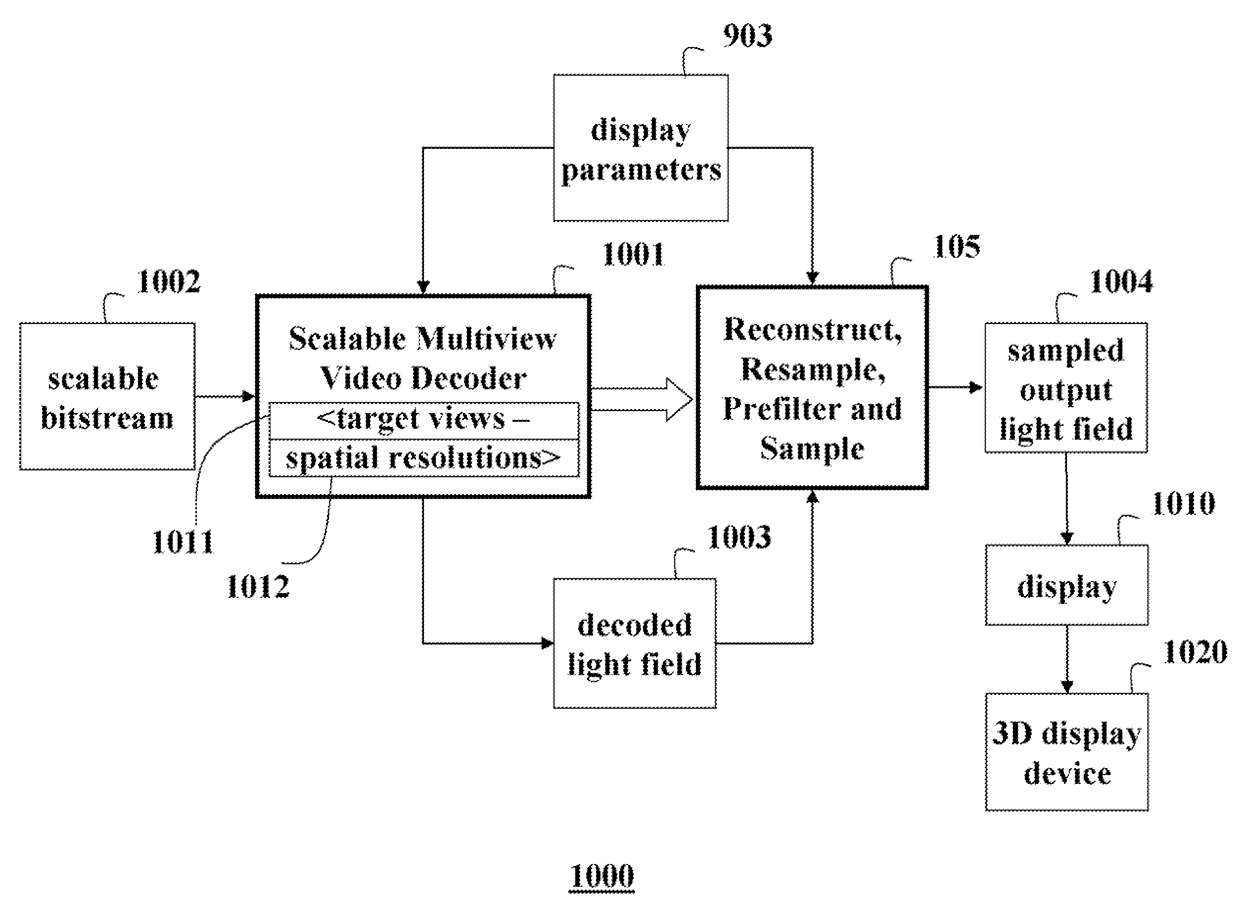
[0129]In this invention, the scalable multi-view video decoder 1001 decodes a subset of views, with the number of views corresponding to a reduced number of views than supported by the display. This might be necessary or desirable under a number of circumstances.

[0130]First, if the required decoding resources to output the number of views supported by the display are not available or would incur long delay, then only a reduced number of views could be provided. Second, it may be more desirable to always have equal baseline distances between spatially adjacent views as output of the decoder, rather than a higher number of decoded views with arbitrary positioning. These instances may arise as a direct result of the prediction dependency between views.

third embodiment

[0131]In this invention, the scalable multi-view video decoder 1001 decodes a subset of views, with the number of views corresponding to a higher number of views than supported by the display. This would be desirable to improve the quality of the oversampled signal, but would require more decoding resources and higher bandwidth. The impact on complexity and bandwidth may be reduced using auxiliary depth maps, which are described in greater detail below.

[0132]Spatial Scalability

[0133]As described above, the spatial resolution of each view affects the spectrum of the input signal. The minimum sampling rate is derived by finding the tightest packing of replicas of the input spectrum such that none of the non-central replicas overlap with the display prefilter. If the number of views to be decoded is determined as described above and acquisition parameters (acquisition parametrization) such as camera aperture are fixed, then the only remaining degree of freedom is the spatial resolution...


PUM


Abstract

A method and system acquire and display light fields. A continuous light field is reconstructed from input samples of an input light field of a 3D scene acquired by cameras according to an acquisition parameterization. The continuous light is reparameterized according to a display parameterization and then prefiltering and sampled to produce output samples having the display parametrization. The output samples are displayed as an output light field using a 3D display device. The reconstruction can be performed by interpolating the input samples having the different views;

Description

RELATED APPLICATIONS[0001]This application is a continuation-in-part of U.S. patent application Ser. No. 11 / 397,227 entitled “Method and System for Acquiring and Displaying 3D Light Fields” and filed by Matusik et al. on Apr. 4, 2006.FIELD OF THE INVENTION[0002]This invention relates generally to acquiring, encoding, decoding and displaying light fields, and more particularly to scalable decoding of 3D light fields, and resampling the reconstructed light fields for display onto automultiscopic display devices.BACKGROUND OF THE INVENTION[0003]It is desired to acquire images of real-world 3D scenes and display them as realistic 3D images. Automultiscopic displays offer uninhibited viewing, i.e., without glasses, of high-resolution stereoscopic images from arbitrary positions in a viewing zone. Automultiscopic displays include view-dependent pixels with different intensities and colors based on the viewing angle. View-dependent pixels can be implemented using conventional high-resoluti...

Claims


Application Information

Patent Timeline
Patent Type & Authority Applications(United States)
IPC IPC(8): H04N15/00G06T19/00H04N13/128
CPCH04N13/0018H04N19/597H04N13/0242H04N13/0022H04N13/243H04N13/122H04N13/128
Inventor VETRO, ANTHONYYEA, SEHOONMATUSIK, WOJCIECHPFISTER, HANSPETERZWICKER, MATTHIAS
Owner MITSUBISHI ELECTRIC RES LAB INC
Why Eureka
Try Eureka