Deformable pipe coupling having multiple radii of curvature

a coupling and curvature technology, applied in the direction of flanged joints, fluid pressure sealed joints, sleeves/socket joints, etc., can solve the problems of manual manipulation of seals, excessive installation process of mechanical couplings, and increased torque requirements

Active Publication Date: 2008-02-28
VICTAULIC
View PDF13 Cites 102 Cited by
  • Summary
  • Abstract
  • Description
  • Claims
  • Application Information

AI Technical Summary

Benefits of technology

[0015]The invention also includes a coupling assembly formed of a plurality of coupling segments as described above, as well as a combination of a pipe c

Problems solved by technology

This geometrical relation between the surface regions of the coupling segments and the outer surfaces of the pipe elements in prior art couplings results in a tedious and time consuming installation process when mechanical couplings are used.
Installation of the ring seal requires that it be lubricated and stret

Method used


Image

  • Deformable pipe coupling having multiple radii of curvature
  • Deformable pipe coupling having multiple radii of curvature
  • Deformable pipe coupling having multiple radii of curvature

Examples


Embodiment Construction

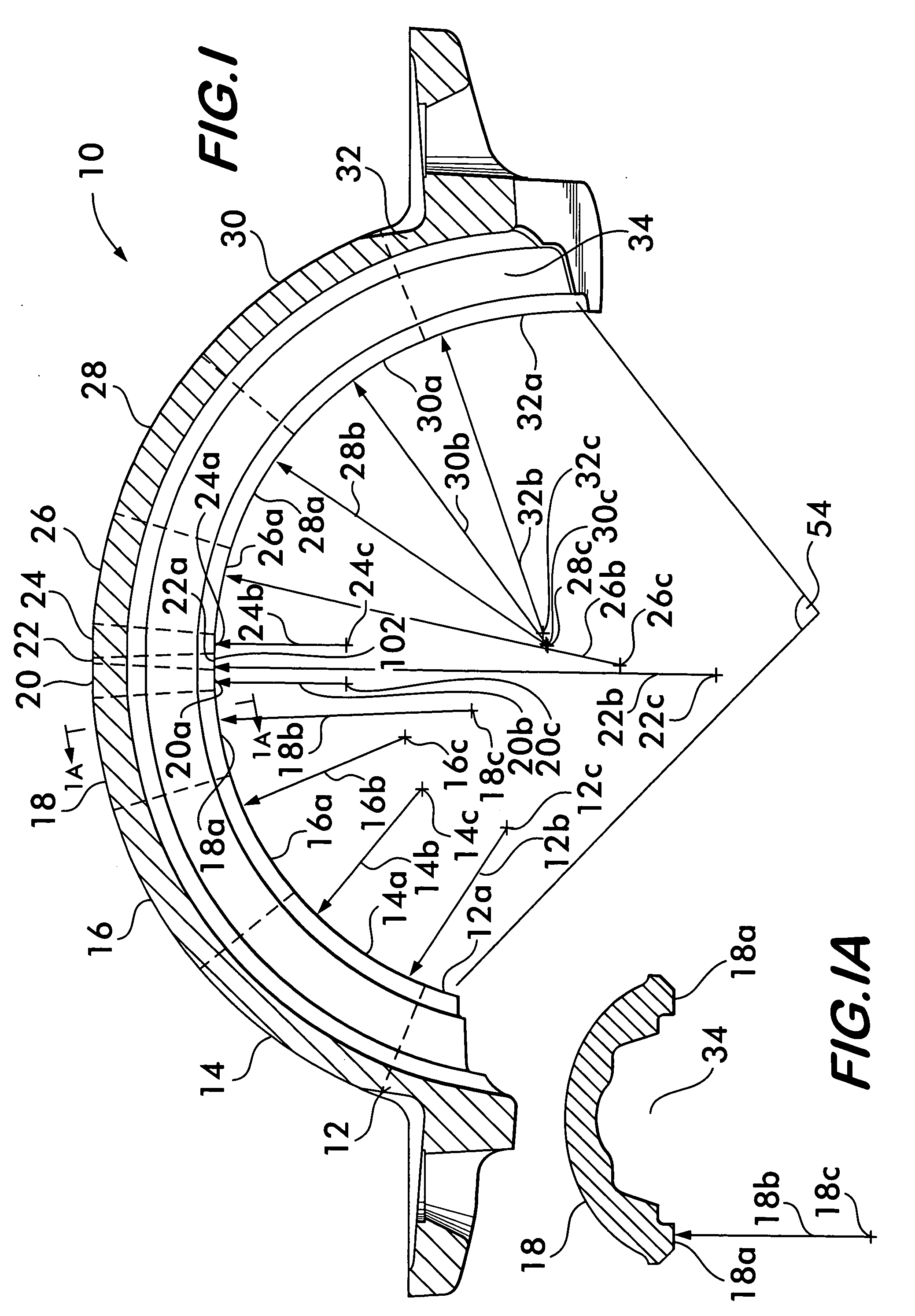
[0035]FIG. 1 shows a pipe coupling segment 10 according to the invention. Coupling segment 10 is formed of a plurality of sub-sections, in this example, eleven sub-sections numbered 12-32 attached to one another end-to-end. Borders between the subsections are denoted for clarity of illustration by broken lines. Each sub-section has a surface region, numbered 12a-32a respectively, the surface regions being disposed so as to interface circumferentially with the outer surfaces of a pipe element for joining pipe elements in end-to-end relation as described in detail below.

[0036]Each surface region has a different radius of curvature from an adjacent surface region on an adjacent sub-section. The radii of curvature for the surface regions are respectively numbered 12b-32b. As a mathematical consequence, each surface region also has a different center of curvature from a surface region on an adjacent sub-section, the centers of curvature being numbered 12c-32c.

[0037]In one embodiment, th...


PUM

PropertyMeasurementUnit
Angleaaaaaaaaaa
Radiusaaaaaaaaaa

Abstract

A pipe coupling for joining pipe elements end-to-end is disclosed. The pipe coupling is formed of segments attached to one another circumferentially straddling the pipe elements. The segments are formed from sub-sections connected to one another end-to-end. Each sub-section has a surface region disposed to engage the outer surfaces of the pipe elements. Each surface region has a different radius of curvature from a surface region on a neighboring sub-section. The radii are selected so that when the coupling segments are deformed around the pipe elements, portions of surface regions of selected sub-sections contact the pipe elements, while portions of surface regions of those sub-sections between the selected portions remain in spaced relation away from the pipe elements. A constant and minimal torque is required to bolt the segments together as a result.

Description

FIELD OF THE INVENTION [0001]The invention relates to mechanical pipe couplings for securing pipe elements to one another end-to-end.BACKGROUND OF THE INVENTION [0002]Mechanical couplings for joining pipe elements together end-to-end comprise interconnectable segments that are positionable circumferentially surrounding the end portions of co-axially aligned pipe elements. The term “pipe element” is used herein to describe any pipe-like item or component having a pipe like form. Pipe elements include pipe stock, pipe fittings such as elbows, caps and tees as well as fluid control components such as valves, reducers, strainers, restrictors, pressure regulators and the like.[0003]Each mechanical coupling segment comprises a housing having arcuate surface regions which are disposed to engage plain end pipe elements or circumferential grooves that extend around each of the pipe elements to be joined. Engagement between the surface regions and the pipe elements provides mechanical restrai...

Claims


Application Information

Patent Timeline
IPC IPC(8): F16L17/00
CPCF16L17/04F16L21/065Y10T29/49936Y10T29/49954F16L23/08
Inventor PORTER, MICHAEL V.HANEY, CRAIGMADARA, SCOTT D.DOLE, DOUGLAS R.PIERCE, JOHN W.
Owner VICTAULIC
Why Eureka
Try Eureka