Oil free screw compressor

a compressor and screw technology, applied in the direction of machines/engines, liquid fuel engines, positive displacement liquid engines, etc., can solve the problems of vibration sound or pulsation sound leakage to the outer side of the package from the surface of the cooler portion, the need for driving system special purpose bases, gear shaft bearings, etc., to improve the assembling characteristic of the compressor and the driving system apparatus. , the effect of downsizing the gear casing

Active Publication Date: 2008-02-28
HITACHI IND EQUIP SYST CO LTD
View PDF6 Cites 8 Cited by
  • Summary
  • Abstract
  • Description
  • Claims
  • Application Information

AI Technical Summary

Benefits of technology

[0010] An object of the present invention is to obtain an oil free screw compressor which can downsize a gear casing as well as improving an assembling characteristic of a compressor and a driving system apparatus.

Problems solved by technology

Further, there is a disadvantage that the driving system special purpose base, the gear shaft, the gear shaft bearing and the like are necessary.
Since the gear casing doubles as a function of an oil reservoir, the gear casing is enlarged in size, so that there is a problem that a high cost is involved by a necessity of a great working equipment.
Further, in the package-shaped oil free screw compressor or the like, since the structured is generally made such that the device such as the cooler or the like constructing the cooling apparatus is exposed to a back surface of the package, or is directly communicated, there is a disadvantage that a vibration sound or a pulsation sound tends to leak to an outer side of the package from a surface of the cooler portion.

Method used


Image

  • Oil free screw compressor
  • Oil free screw compressor
  • Oil free screw compressor

Examples


embodiment 1

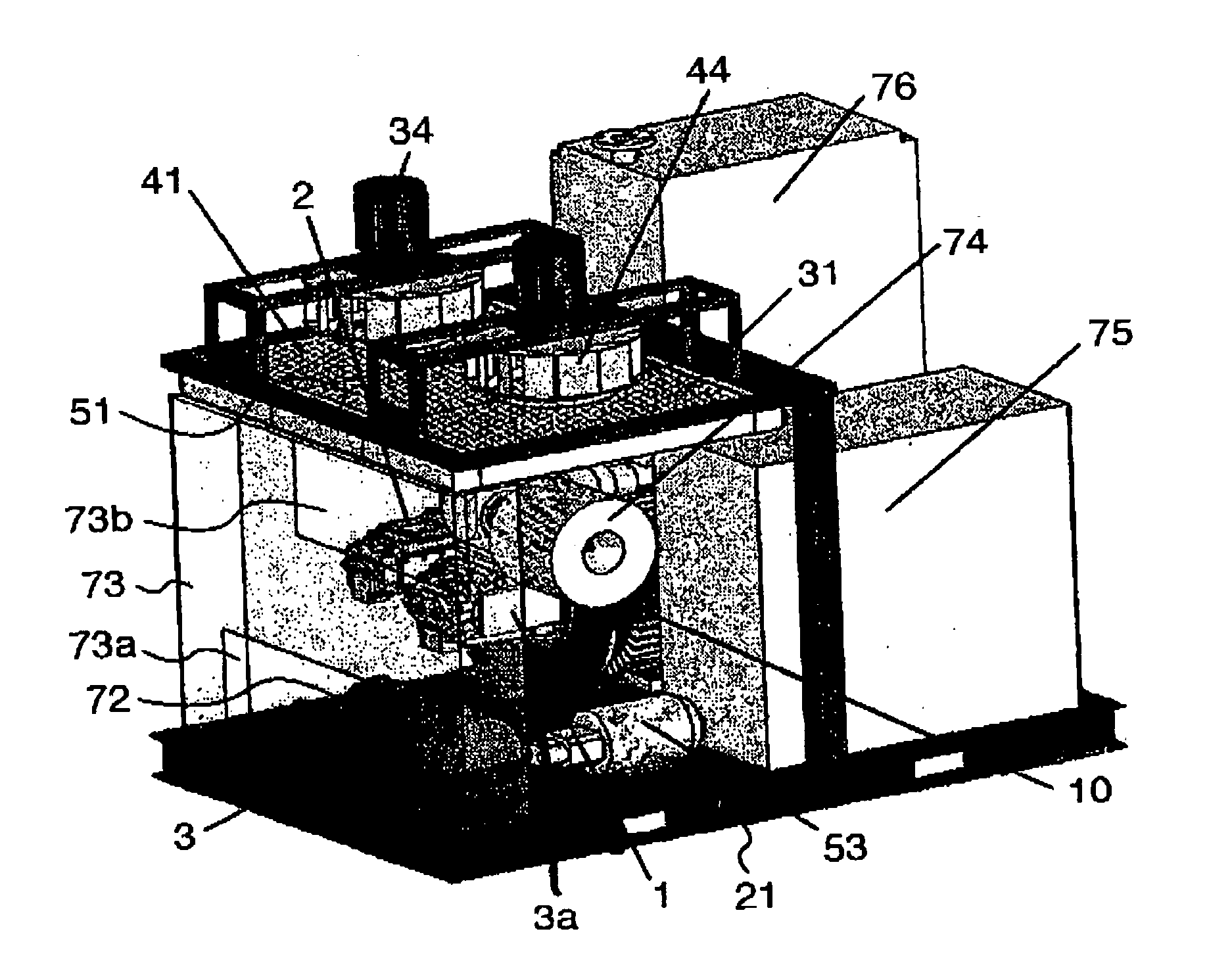
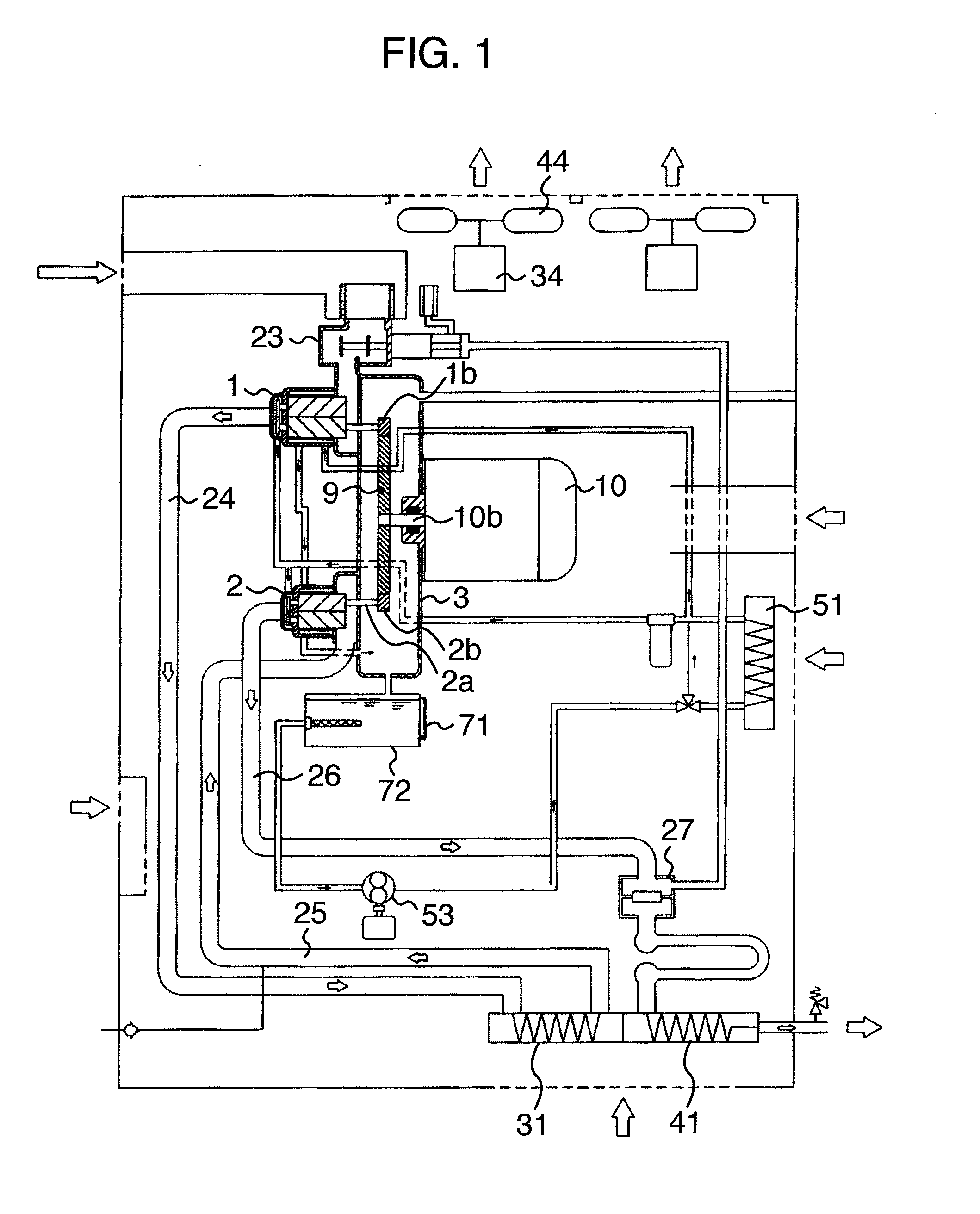
[0057]FIG. 1 is a system view showing a whole structure of an oil free screw compressor in accordance with the present embodiment, and shows an example in the case of applying the present invention to an air-cooled type two-stage oil free screw compressor.

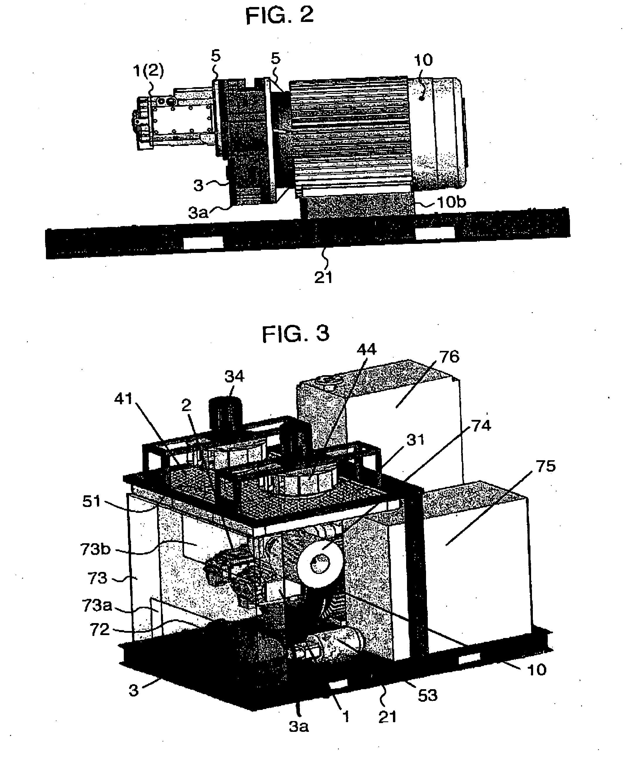
[0058] The air-cooled type two-stage oil free screw compressor is provided with a low pressure stage side compressor airend 1 and a high pressure stage side compressor airend 2, and these compressor main bodies 1 and 2 are coupled to a motor shaft 10a of a motor 10. A gear casing 3 is provided with a bull gear 9 attached to a shaft leading end of the motor shaft 10a, and pinion gears 1b and 2b attached to leading ends of rotation driven shafts 1a and 2a of the compressor main bodies 1 and 2 and engaging with the bull gear 9. When the motor 10 is rotated, a rotating force thereof is transmitted to the compressor main bodies 1 and 2 via the bull gear 9 and the pinion gears 1b and 2b so as to rotate the compressor main bodies 1 and 2...


PUM


Abstract

The invention downsizes and simplifies structures of a compressor and its driving system apparatus, and achieves a reduction of a noise. An oil free screw compressor is constituted by compressor main bodies compressing a gas, a motor driving rotors of the compressor main bodies via step-up gears, a gear casing storing the step-up gears, cooling apparatuses cooling a discharge air and the like. An oil tank is provided independently from the gear casing, the motor is fixed to a common base, the gear casing is integrally attached to the motor via a flange, and the compressor main bodies are integrally attached to the gear casing via the flange. Further, the cooling apparatuses are arranged in an upper side of the driving system apparatus, and a cooling fan is installed in an upper side thereof.

Description

INCORPORATION BY REFERENCE [0001] The present application claims priority from Japanese application JP2006-196410 filed on Jul. 19, 2006, the content of which is hereby incorporated by reference into this application. BACKGROUND OF THE INVENTION [0002] 1. Field of the Invention [0003] The present invention relates to an oil free screw compressor having a compressor airend compressing a gas such as an air or the like, a driving apparatus driving the compressor airend, a cooling device cooling the gas discharged from the compressor airend and the like, and is particularly suitable for a middle capacity package type oil free screw compressor provided with a low pressure stage compressor airend and a high pressure stage compressor airend. [0004] 2. Description of Related Art [0005] As one example of the conventional middle capacity oil free screw compressor, there is a structure described in patent document 1 (JP-A-2002-155879 (FIG. 1)). In this conventional structure, a gear shaft with...

Claims


Application Information

Patent Timeline
Patent Type & Authority Applications(United States)
IPC IPC(8): F04C23/00
CPCF04C29/04F04C23/00F04C18/16
Inventor KAWABATA, NATSUKINISHIMURA, HITOSHINAGAI, YUSUKE
Owner HITACHI IND EQUIP SYST CO LTD
Why Eureka
Try Eureka