Raw material vaporizing and supplying apparatus

a technology of supplying apparatus and raw materials, which is applied in the direction of liquid surface applicators, coatings, metal material coating processes, etc., can solve the problems of reducing the accuracy of flow rate control, temperature fluctuation, and many unsolved problems, so as to achieve high-quality semiconductor products, accurately and easily control the concentration of raw material gas, and supply raw material gas stably

Inactive Publication Date: 2014-08-07
FUJIKIN INC
View PDF11 Cites 9 Cited by
  • Summary
  • Abstract
  • Description
  • Claims
  • Application Information

AI Technical Summary

Benefits of technology

[0033]The present invention is configured such that the raw material gas inside the source tank is directly supplied to the process chamber while performing flow rate control by the pressure type flow rate control system.
[0034]As a result, it is possible to always supply only pure raw material gas toward the process chamber, and it is possible to highly accurately and easily control a concentration of raw material gas in process gas as compared with a conventional raw material vaporizing and supplying apparatus using a bubbling method or a vaporizing method, which makes it possible to manufacture high quality semiconductor products.
[0035]Further, because the pressure type flow rate control system is used, troubles are hardly ever caused due to clogging or the like by raw material gas condensation as in a mass flow controller (thermal type mass flow rate control system), which makes it possible to stably supply raw material gas as compared with a conventional raw material vaporizing and supplying apparatus using a thermal type mass flow rate control system.
[0036]Moreover, because the pressure type flow rate control system has the characteristics of being less likely to be affected by a pressure fluctuation in the primary side supply source, even when the raw material gas pressure in the source tank slightly fluctuates, it is possible to perform highly accurate flow rate control.
[0037]In addition, the source tank and the pressure type flow rate control system are integrally assembled fixedly so as to be disengageable, thereby it is possible to significantly downsize the raw material vaporizing and supplying apparatus, and lower the manufacturing cost.

Problems solved by technology

In contrast thereto, a raw material vaporizing and supplying apparatus using a baking method in which raw material gas is generated by warming, and the saturated gas is supplied to a location using raw material, has a host of problems in regards to stability in generation of raw material gas, control of gas quantity and gas pressure of the raw material gas, flow rate control of the raw material gas(raw material gas or steam), and the like.
However, because a raw material vaporizing and supplying apparatus using a baking method is configured to supply raw material gas (raw material gas or steam) at a saturated gas pressure generated from a raw material, directly to a process chamber, various disadvantages are avoided that are caused by a fluctuation in concentration of a raw material gas in process gas, such as are presentin a raw material vaporizing and supplying apparatus using a bubbling method.
However, there remain many unsolved problems in the raw material vaporizing and supplying apparatus shown in FIG. 15 as well.
The first problem regards the accuracy of flow rate control and stability of flow rate control of the raw material gas G0 to be supplied to the process chamber 37.
Therefore, it is unavoidable to cause a temperature fluctuation in the gas G0′ flowing in the ultrafine sensor pipe 32e.
), not only a reduction in accuracy of flow rate control, but also liquescence of the gas G0′ in the portion of the sensor pipe 32e, clogging of the gas G0′ thereby are easily caused, which poses a problem for stable supply of the raw material gas G0.
The second problem regards the increase in size of raw material vaporizing and supplying apparatuses.
As a result, the problem is that the installation spaces for the respective members composing the raw material vaporizing and supplying apparatus are relatively increased, which makes it impossible to significantly downsize the raw material vaporizing and supplying apparatus.

Method used


Image

  • Raw material vaporizing and supplying apparatus
  • Raw material vaporizing and supplying apparatus
  • Raw material vaporizing and supplying apparatus

Examples


example 1

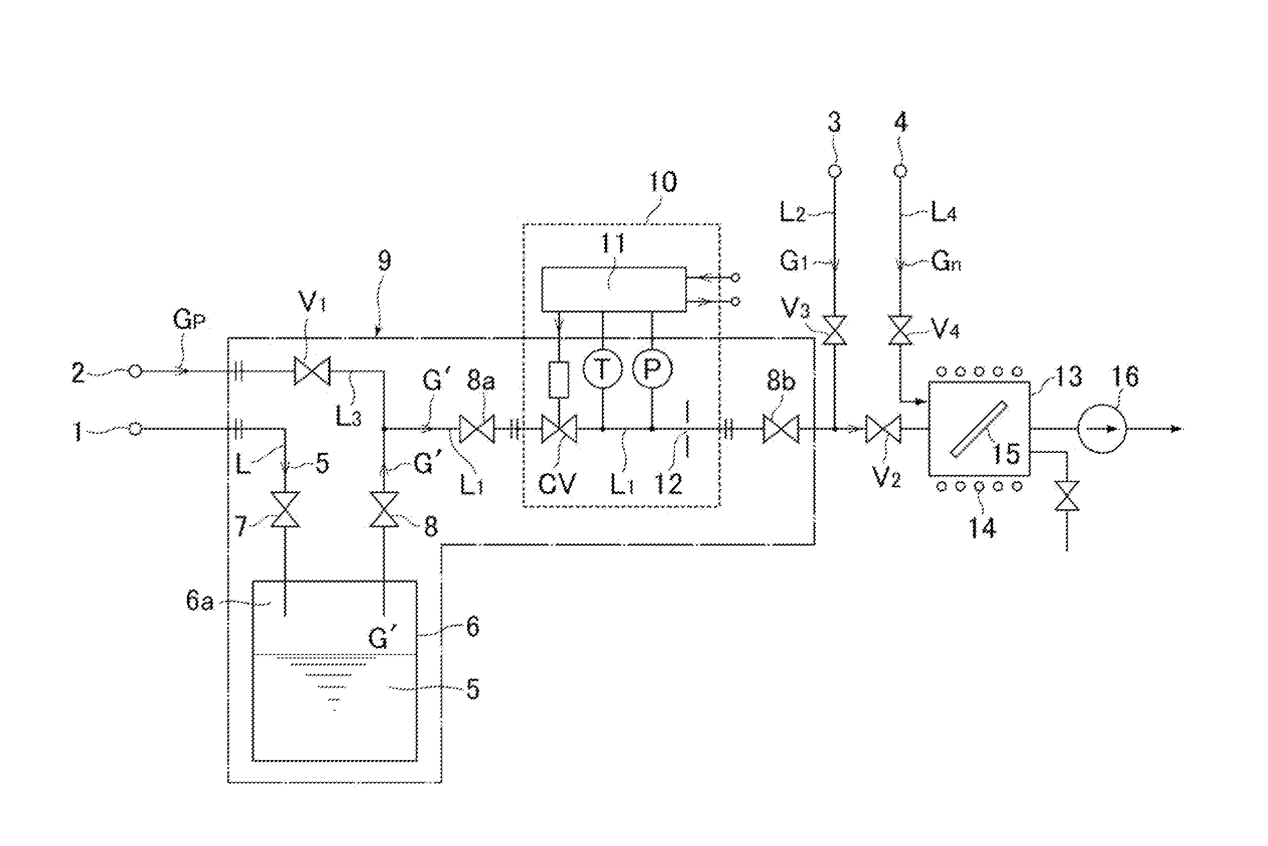
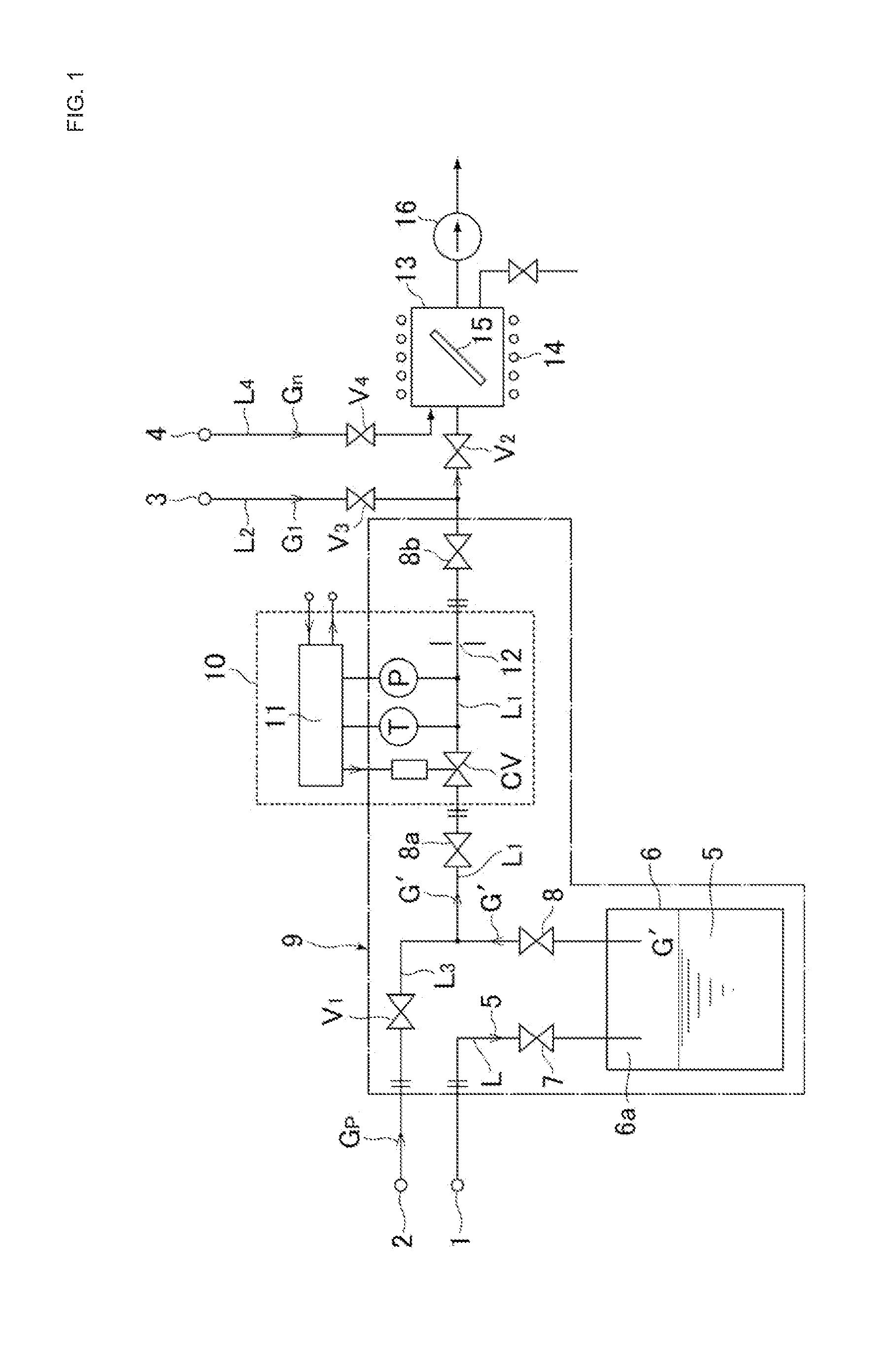
[0070]The source tank 6 and the pressure type flow rate control system 10 were installed as shown in FIG. 4, and the flow rate control characteristics of the raw material gas by the pressure type flow rate control system 10 were tested.

[0071]First, a cylindrical tank (internal capacity of 100 ml) made of stainless steel was prepared as the source tank 6, and as the raw material 5, trimethylgallium (TMGa / manufactured by Ube Industries, Ltd.) of 80 ml was made to flow into the tank.

[0072]The TMGa raw material 5 is in liquid form at room temperature, and is a pyrophoric material having the physical properties: its melting point / freezing point is −15.8° C., its boiling point is 56.0° C., its gas pressure is 22.9 KPa (20° C.), its specific gravity is 1151 kg / m3 (15° C.), and the like.

[0073]Further, as the pressure type flow rate control system 10, the FCSP7002-HT50-F450A model (in the case of TMGa gas flow rate of 21.9 to 109.3 sccm) and the F88A model (in the case of TMGa gas flow rate ...


PUM

PropertyMeasurementUnit
temperatureaaaaaaaaaa
boiling pointaaaaaaaaaa

Abstract

A raw material vaporizing and supplying apparatus including a source tank in which a raw material is stored, a raw material gas supply channel through which raw material gas is supplied from an internal space portion of the source tank to a process chamber, a pressure type flow rate control system which is installed along the way of the supply channel, and controls a flow rate of the raw material gas which is supplied to the process chamber, and a constant temperature heating unit that heats the source tank, the supply channel, and the pressure type flow rate control system to a set temperature, wherein the raw material gas generated in an internal space portion of the source tank is supplied to the process chamber while the pressure type flow rate control system performs flow rate control.

Description

[0001]This is Continuation-in-Part Application in the United States of International Patent Application No. PCT / JP2012 / 003783 filed Jun. 11, 2012, which claims priority on Japanese Patent Application No. 2011-167915, filed Aug. 1, 2011. The entire disclosures of the above patent applications are hereby incorporated by reference.BACKGROUND OF THE INVENTION[0002]1. Technical Field[0003]The present invention relates to an improvement in a raw material vaporizing and supplying apparatus of semiconductor manufacturing equipment using so-called metalorganic chemical vapor deposition (hereinafter called MOCVD), and more particularly, relates to a raw material vaporizing and supplying apparatus which is capable of supplying raw material gas while highly accurately performing flow rate control of even a liquid or solid raw material at a low gas pressure, to a set flow rate, and which makes it possible to significantly simplify and downsize the apparatus structure.[0004]2. Description of the ...

Claims


Application Information

Patent Timeline
Patent Type & Authority Applications(United States)
IPC IPC(8): C23C16/448
CPCC23C16/4485C23C16/4482
Inventor NAGASE, MASAAKIHIDAKA, ATSUSHIHIRATA, KAORUDOHI, RYOUSUKENISHINO, KOUJIIKEDA, NOBUKAZU
Owner FUJIKIN INC
Why Eureka
Try Eureka