Pressing terminal and terminal pressing device

a pressing device and pressing terminal technology, applied in the direction of metal working apparatus, connection formation by deformation, manufacturing tools, etc., can solve the problems of difficult to precisely obtain the space for a wiring process, difficult to downsize enlarge the dimensions of the electrical connector as a whole, so as to reduce the clearance, reduce the size of the pressing terminal, and achieve the effect of precise space for the wiring process

Inactive Publication Date: 2010-12-23
HIROSE ELECTRIC GROUP
View PDF8 Cites 9 Cited by
  • Summary
  • Abstract
  • Description
  • Claims
  • Application Information

AI Technical Summary

Benefits of technology

[0052]Accordingly, it is possible to eliminate the clearance between the outer circumference surface of the dielectric member and the inner circumference surface the shield outer tube. As a result, the pressing piece of the signal line pressing portion of the inner conductive member can be situated in the pressing tool insertion opening portion without shifting from the center of the pressing tool insertion opening portion.
[0053]The signal line crimper and the signal line anvil swage the pressing piece of the signal line pressing portion in the pressing tool insertion opening portion in such a state. Therefore, it is possible to obtain the precise space for the wiring process. Consequently, it is not necessary to design pressing tools (the signal line anvil and the signal line crimper) so that the pressing teeth thereof do not interfere with the pressing piece, in order to obtain the space for the wiring process. Accordingly, it is possible to downsize the pressing terminal. Eventually, it is possible to downsize the connector including such that pressing terminal (for example, the connector plug), and the electrical connector as a whole.

Problems solved by technology

Therefore, it is not easy to obtain a space for a wiring process precisely.
Therefore, it is difficult to downsize the electrical connector as a whole.
Accordingly, it is not possible to downsize the pressing terminal 112, resulting in enlarging dimensions of the electrical connector as a whole.
Therefore, it is difficult to downsize the electrical connector as a whole.
Consequently, it is difficult to make the tip portion of the signal line crimper 122 finer.
As a result, it is difficult to downsize the pressing terminal 112, resulting in enlarging dimensions of the electrical connector as a whole.
Therefore, it is difficult to downsize the electrical connector as a whole.
Therefore, it is difficult to make the tip portion of the signal line crimper 122 finer.
As a result, it is difficult to downsize the pressing terminal 112, resulting in enlarging dimensions of the electrical connector as a whole.
Therefore, it is difficult to downsize the electrical connector as a whole.

Method used


Image

  • Pressing terminal and terminal pressing device
  • Pressing terminal and terminal pressing device
  • Pressing terminal and terminal pressing device

Examples


Embodiment Construction

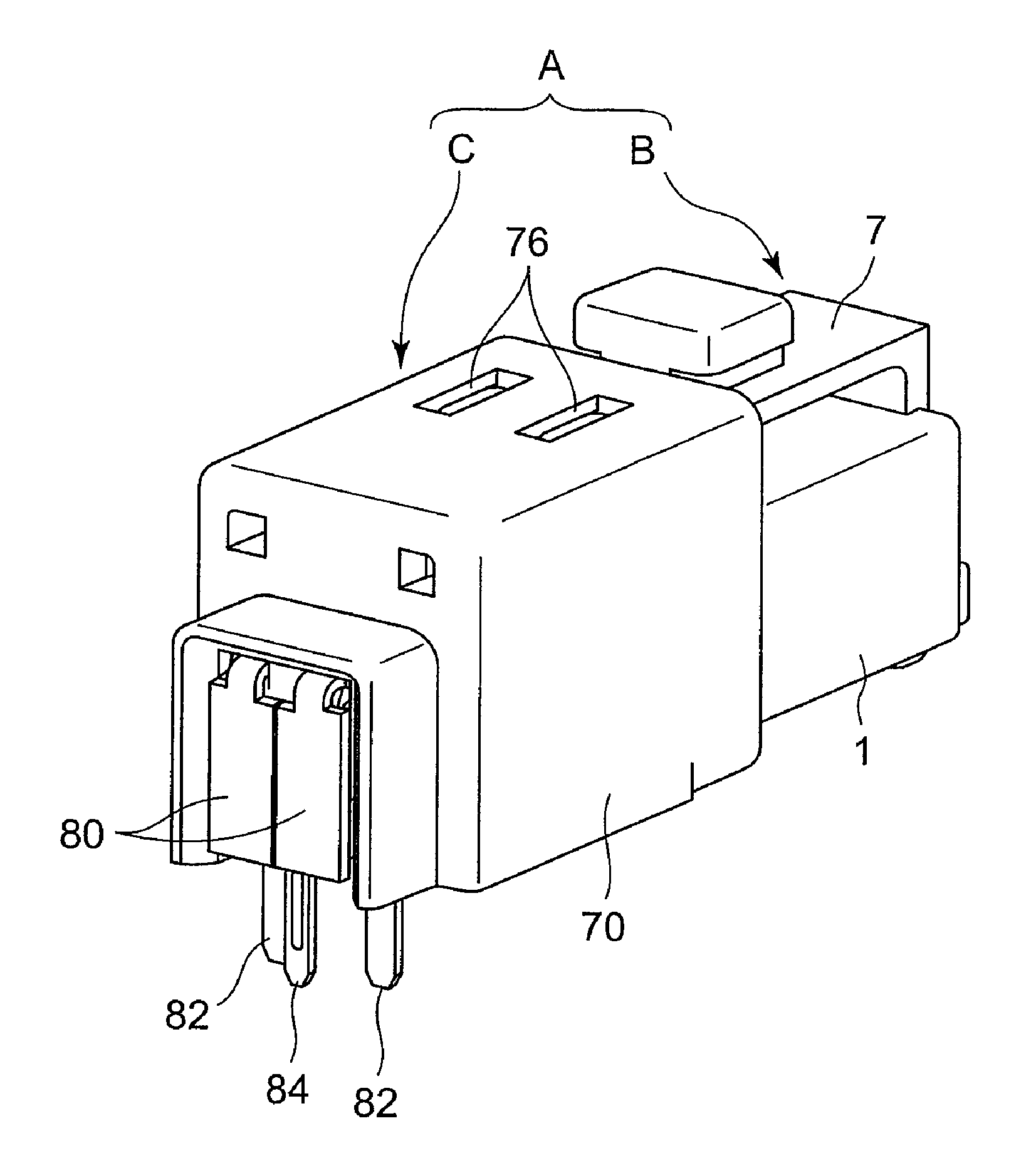
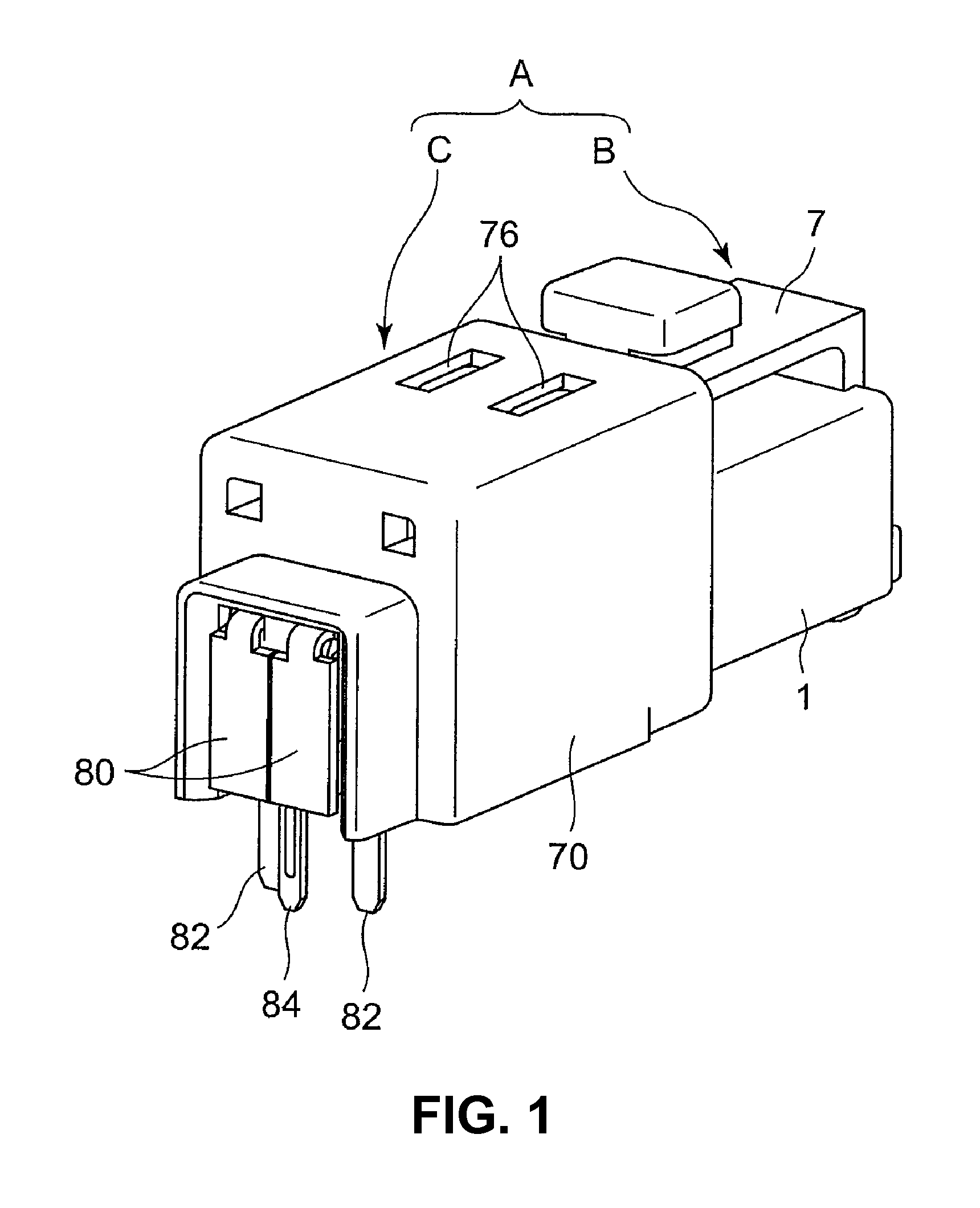
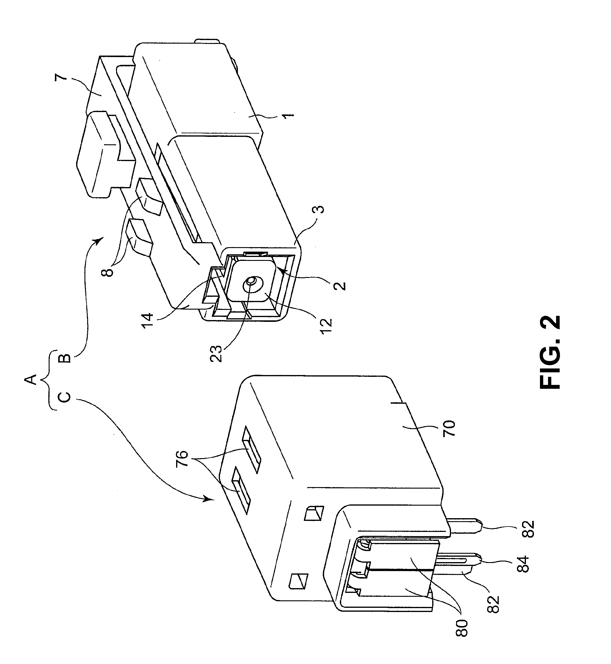
[0077]Embodiments of the present invention will be explained with reference to the accompanying drawings.

[0078]When an inner conductive member is held in a shield outer tube via a dielectric member, the dielectric member holding the inner conductive member is forcibly inserted into the shield outer tube with a protruding portion thereof sliding and being ground against an inner surface of the shield outer tube. Accordingly, it is possible to eliminate a clearance between an outer circumference surface of the dielectric member and an inner circumference surface the shield outer tube. As a result, it is possible to obtain a space for a wiring process precisely. Consequently, it is not necessary to design pressing tools (a signal line anvil and a signal line crimper) so that pressing teeth thereof do not interfere with the pressing piece. Accordingly, it is possible to downsize the pressing terminal. Thereby, an object to downsize the pressing terminal, the connector including such tha...


PUM

PropertyMeasurementUnit
pressureaaaaaaaaaa
thickaaaaaaaaaa
conductiveaaaaaaaaaa

Abstract

A pressing terminal includes an outer conductive member having a shield outer tube; an inner conductive member; and a dielectric member. The dielectric member includes a protruding portion fitted into the shield outer tube so that a signal line pressing portion of the inner conductive member is situated at a pressing tool insertion opening portion. The dielectric member is inserted into a shield outer tube with the protruding portion thereof sliding against the shield outer tube. A terminal pressing device includes an anvil unit and a crimper unit. Upon attaching the signal wire, a claw portion of a signal line crimper of the crimper unit is inserted into a claw insertion groove portion of a signal line anvil of the anvil unit. A terminal pressing anvil portion of the signal line anvil is ushered to a terminal pressing anvil insertion portion of the signal line crimper.

Description

BACKGROUND OF THE INVENTION AND RELATED ART STATEMENT[0001]The present invention relates to a pressing terminal provided in an electrical connector which is used for an electronic control device and the like, and a terminal pressing device for pressing the pressing terminal to a shield wire.[0002]As shown in FIG. 19, in a conventional electrical connector, a connector socket 100 includes a socket connecting portion 103 in which a socket contacting terminal or a mating terminal 101 is attached to a socket insulating housing 102. The mating pressing terminal 101 includes a mating outer conductive member 105 and a mating inner conductive member 106. The mating outer conductive member 105 includes a shield outer tube 107. The shield outer tube 107 includes a shield contact terminal 108, a piece having a tongue-like shape formed by cutting and raising a central portion of both side surfaces thereof.[0003]In addition, as shown in FIG. 19, in the conventional electrical connector, a connec...

Claims


Application Information

Patent Timeline
Patent Type & Authority Applications(United States)
IPC IPC(8): H01R43/04
CPCH01R4/185H01R9/0518Y10T29/53226Y10T29/53235H01R43/048
Inventor TAKAHASHI, MAORIOKADA, MASAO
Owner HIROSE ELECTRIC GROUP
Why Eureka
Try Eureka