Illumination device

Active Publication Date: 2019-07-04
MITSUBISHI ELECTRIC CORP
View PDF0 Cites 9 Cited by
  • Summary
  • Abstract
  • Description
  • Claims
  • Application Information

AI Technical Summary

Benefits of technology

[0011]The present invention can

Problems solved by technology

When an optical part is mounted to a holder for holding a part or the like so that it can withstand vibration of the vehicle, deformation of the part due to

Method used


Image

  • Illumination device
  • Illumination device
  • Illumination device

Examples


first embodiment

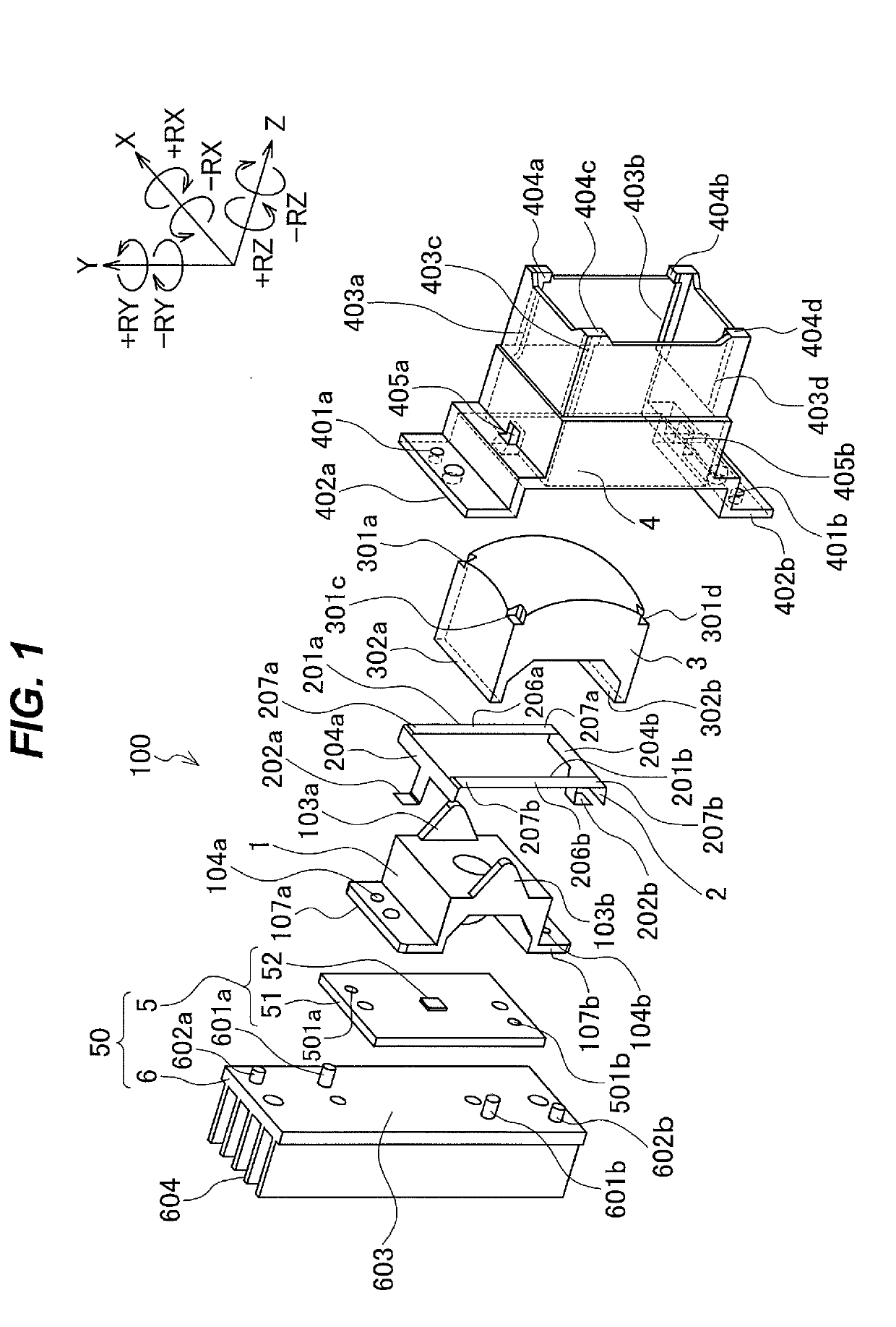
[0041]The following embodiments and modification examples describe headlights as examples.

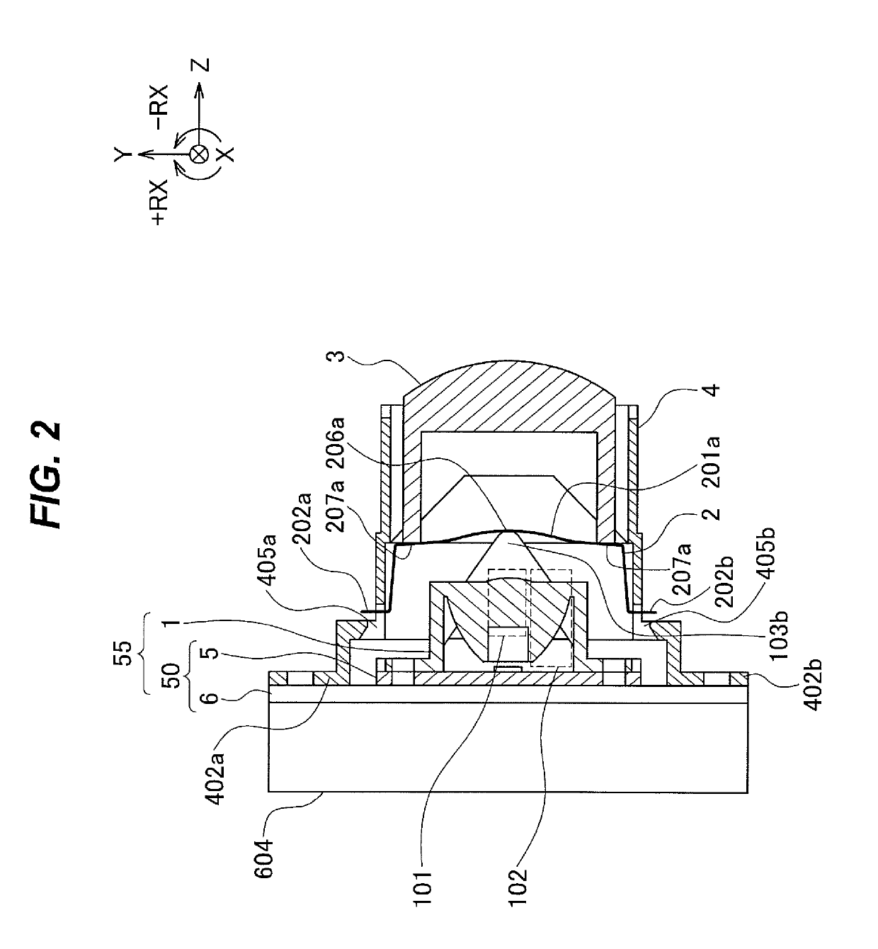
[0042]FIG. 1 is a front exploded perspective view of a headlight 100 according to a first embodiment. FIG. 2 is a side sectional view of the headlight 100 in an assembled state. FIG. 3 is a side sectional view of a holder 4 according to the first embodiment.

[0043]To facilitate description, XYZ-orthogonal coordinate axes are shown in each drawing. In the following description, it is assumed that a forward direction of the headlight 100 is the +Z axis direction and a backward direction is the −Z axis direction. A direction in which the headlight 100 projects light is the +Z axis direction. It is assumed that in a state where the headlight 100 is mounted on a vehicle or the like, as one faces in the forward direction (+Z axis direction), a leftward direction of the headlight 100 is the +X axis direction and a rightward direction is the −X axis direction. It is assumed that an upward direction (dir...

first modification example

[0159]FIG. 6 is a front exploded perspective view of a headlight 110.

[0160]The headlight 110 includes a condensing lens 1, a spring member 230, a projection lens 330, a holder 4, and a light emitter 5. The headlight 110 may include a heat dissipation unit 6. The condensing lens 1, holder 4, light emitter 5, and heat dissipation unit 6 are the same as those of the headlight 100. The condensing lens 1 and light emitter 5 are held on the heat dissipation unit 6 in the same manner as in the headlight 100.

[0161]The spring member 230 differs from the spring member 2 in having two holding portions 205a and 205b and holding holes 203a and 203b. Otherwise, the spring member 230 has the same configuration as the spring member 2.

[0162]The spring member 230 includes the holding portions 205a and 205b. The holding portions 205 have, for example, plate shapes. As illustrated in FIG. 6, the holding portions 205 are disposed parallel to a Z-X plane. The holding portions 205 have shapes extending fr...

second modification example

[0181]FIG. 8 is a front exploded perspective view of a headlight 120.

[0182]The headlight 120 includes a condensing lens 1a, a spring member 250, a second lens 3, a holder 4, and a light emitter 5. The headlight 120 may include a heat dissipation unit 6. The projection lens 3, holder 4, light emitter 5, and heat dissipation unit 6 have the same configuration as those of the headlight 100. The condensing lens 1a and light emitter 5 are fixed to the heat dissipation unit 6 in the same manner as in the headlight 100.

[0183]The condensing lens 1a differs from the condensing lens 1 in having projections 105a and 105b. The projections 105a and 105b have inclined surfaces 106a and 106b. Otherwise, the condensing lens 1a has the same configuration as the condensing lens 1.

[0184]The projections 105 are used for temporarily assembling the spring member 250 to the condensing lens 1a.

[0185]The projection 105a is disposed on a side surface of the condensing lens 1a on the +Y axis side. The projec...


PUM


Abstract

An illumination device including: a light source including a light emitting element that emits light; a first optical element that transmits the light; a second optical element that transmits the light transmitted by the first optical element; a holder that holds the second optical element; and a spring member including at least one spring portion that generates spring force by being deflected, the spring member pressing the second optical element against the holder with the spring force to hold the second optical element against the holder, wherein the first optical element and the second optical element deflect a center portion in a long edge direction of the at least one spring portion with respect to ends in the long edge direction of the at least one spring portion.

Description

TECHNICAL FIELD[0001]The present invention relates to an illumination device.BACKGROUND ART[0002]From the viewpoint of reducing the burden on the environment, such as reducing emission of carbon dioxide (CO2) and consumption of fuel, it is desired to improve energy efficiency of vehicles. Accordingly, for example, in vehicle headlight devices (referred to below as headlights) or the like, downsizing, weight reduction, and power efficiency improvement are required. “Headlight” refers to an illuminating device that is mounted on a transportation machine or the like and used to improve visibility for an operator and conspicuity to the outside. A vehicle headlight is also referred to as a headlamp or headlight.[0003]Thus, when a headlight is taken as an example, it is desired to employ, as a light source, a semiconductor light source having higher luminous efficiency than conventional halogen bulbs (lamp light sources). “Semiconductor light source” refers to, for example, a light emitti...

Claims


Application Information

Patent Timeline
IPC IPC(8): G02B7/02F21S41/27B60Q1/04F21V17/06F21S41/32F21S41/141
CPCG02B7/021F21S41/27B60Q1/04F21V17/06F21S41/32F21S41/141F21V17/00F21V19/00G02B7/00G02B7/02F21V17/164F21Y2115/10F21S41/29F21V17/162
Inventor OSHIMA, RITSUYASUWA, MASASHIGENAKAMURA, KEIJIKUWATA, MUNEHARU
Owner MITSUBISHI ELECTRIC CORP
Why Eureka
Try Eureka