E-fuse bar code structure and method of using the same

a bar code and bar code technology, applied in the field of e-fuse bar code structure and a method of using the same, can solve the problems of high environmental demands, complicated reading devices, and high cost, and achieve the effect of compact size and downsiz

Inactive Publication Date: 2008-06-19
UNITED MICROELECTRONICS CORP
View PDF6 Cites 8 Cited by
  • Summary
  • Abstract
  • Description
  • Claims
  • Application Information

AI Technical Summary

Benefits of technology

[0017]The eFuse bar code structure in accordance with the present invention uses eFuses as a bar pattern. The eFuses can be manufactured by semiconductor processes. The advantages are to downsize to a small and to have compact size and the ability to store a lot of information in a unit volume. Voltages are applied on the junctions to blow the fuses. It is convenient to use electric signals or optical scanning to read the information. Due to the fact that a lot of information is stored in a unit volume, information in Chinese may be saved through proper encoding and decoding methods. In addition, batch information is possible. In other words, information can be added to the same bar code structure successively.

Problems solved by technology

Magnetic stripes are useful in information storage, but high environmental demands, complicated reading devices and high cost are the disadvantages.
However, they are vulnerable, susceptible to magnetic fields, and need special care.
However, the current demand of bar codes being light, thin, short, small, and compact and high reliability is increasing.
With the miniaturization of semiconductor production and the increase of elaborateness, semiconductor devices are more susceptible to all kinds of defects and impurities.
Failure of a single interconnect, diode or transistor will lead to the defect of the entire wafer.

Method used


Image

  • E-fuse bar code structure and method of using the same
  • E-fuse bar code structure and method of using the same
  • E-fuse bar code structure and method of using the same

Examples


Embodiment Construction

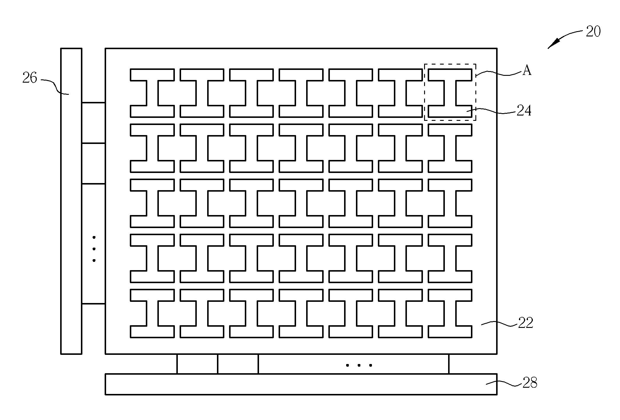
[0029]Please refer to FIG. 5. FIG. 5 is a top view of an embodiment of the eFuse bar code structure according to the present invention. The eFuse bar code structure 20 comprises a substrate 22 and a plurality of eFuse elements 24 disposed on substrate 22. The substrate 22 may be a semiconductor substrate for facilitating the production of the eFuse elements. The eFuse elements 24 may be one-dimensionally, two-dimensionally or three-dimensionally (i.e. multi-layer) arranged in a form of an array. FIG. 5 illustrates an example of two-dimensional arrangement. The eFuse bar code structure 20 may further comprise a plurality of electric circuits for separately electrically connecting the eFuse elements to an external circuit. For example, in the case of reading process, it may be electrically connected to row decoder 26 and column decoder 28 for decoding. It may be connected to a signal amplifier for amplifying signals.

[0030]FIG. 6 illustrates the A section of the eFuse bar code structur...


PUM


Abstract

An invention relating to an eFuse bar code structure and a method of using the bar code structure is disclosed. The bar code structure includes a substrate and a plurality of eFuse elements disposed on the substrate and arranged in a form of an array, such that a bar pattern can be formed by the result of whether the fuse of the eFuse elements is blown or not. The method of using the bar code structure includes, with respect to a data, fuses of the eFuse elements in the bar code structure being correspondingly blown in accordance with an encoding method to form a bar pattern. The eFuse bar code structure according to the present invention can be manufactured by using a semiconductor manufacturing process, and thus it has small volume, a high density and may record a huge number of data.

Description

BACKGROUND OF THE INVENTION[0001]1. Field of the Invention[0002]The present invention relates to an e-fuse bar code structure and a method of using the bar code. More particularly, the present invention relates to a bar code structure using eFuses as a bar pattern and a method of using the same.[0003]2. Description of the Prior Art[0004]With the development of technology, it is desirable that the information regarding the raw materials, production and marketing of a product may be given for the record for inquiry or identification to facilitate the administration of manufactures, suppliers and the usage of consumers. The current solutions include Automatic Data Collection (ADC) such as bar codes, magnetic stripes, IC cards, etc. The data can be input into a database without the help of keyboards.[0005]Magnetic stripes are useful in information storage, but high environmental demands, complicated reading devices and high cost are the disadvantages. Smart cards, i.e. IC cards, are int...

Claims


Application Information

Patent Timeline
Patent Type & Authority Applications(United States)
IPC IPC(8): G06K19/06
CPCG06K19/06028G06K19/067G06K19/06046
Inventor WU, PING-CHANG
Owner UNITED MICROELECTRONICS CORP
Why Eureka
Try Eureka