Modular intervertebral disc prosthesis and method of replacing an intervertebral disc

Inactive Publication Date: 2008-02-28
DWYER JAMES
View PDF7 Cites 160 Cited by
  • Summary
  • Abstract
  • Description
  • Claims
  • Application Information

AI Technical Summary

Problems solved by technology

In some instances, genetic or developmental irregularities, trauma, chronic stress or degenerative disease can result in spinal pathologies necessitating removal of an intervertebral disc.
With this design, however, the fixation between the metal plates and the bone is inadequat

Method used


Image

  • Modular intervertebral disc prosthesis and method of replacing an intervertebral disc
  • Modular intervertebral disc prosthesis and method of replacing an intervertebral disc
  • Modular intervertebral disc prosthesis and method of replacing an intervertebral disc

Examples


Embodiment Construction

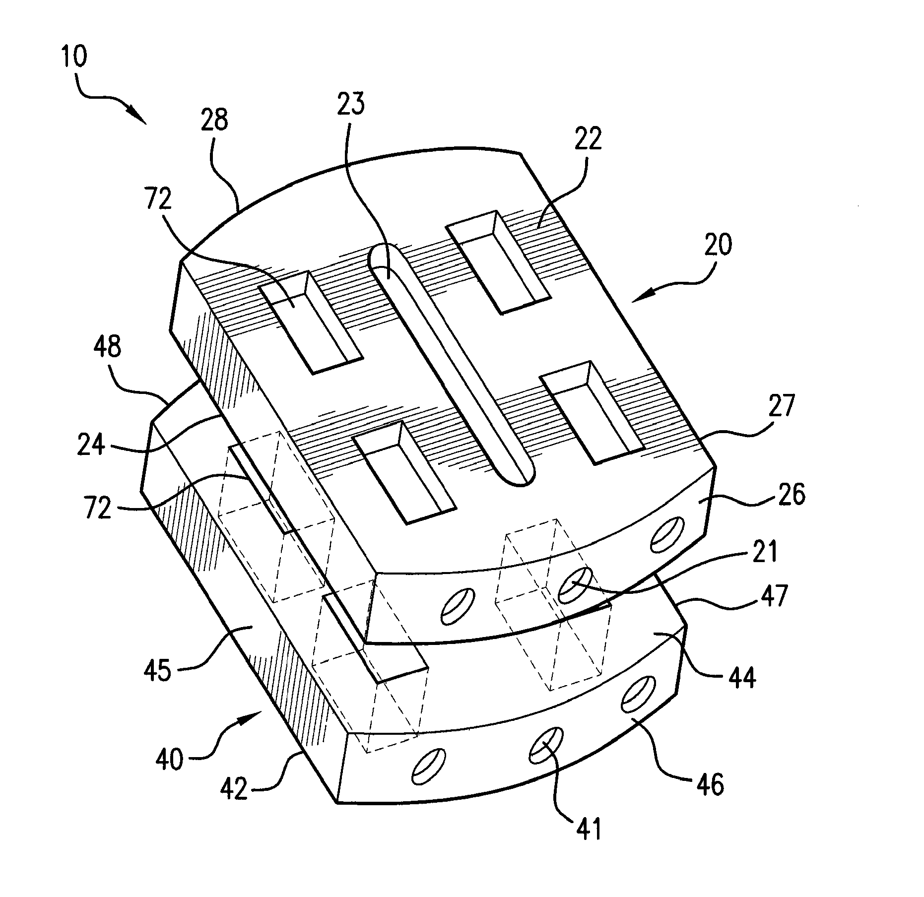
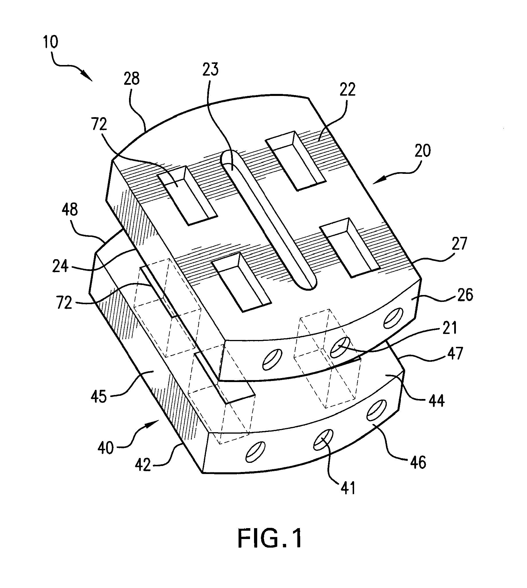
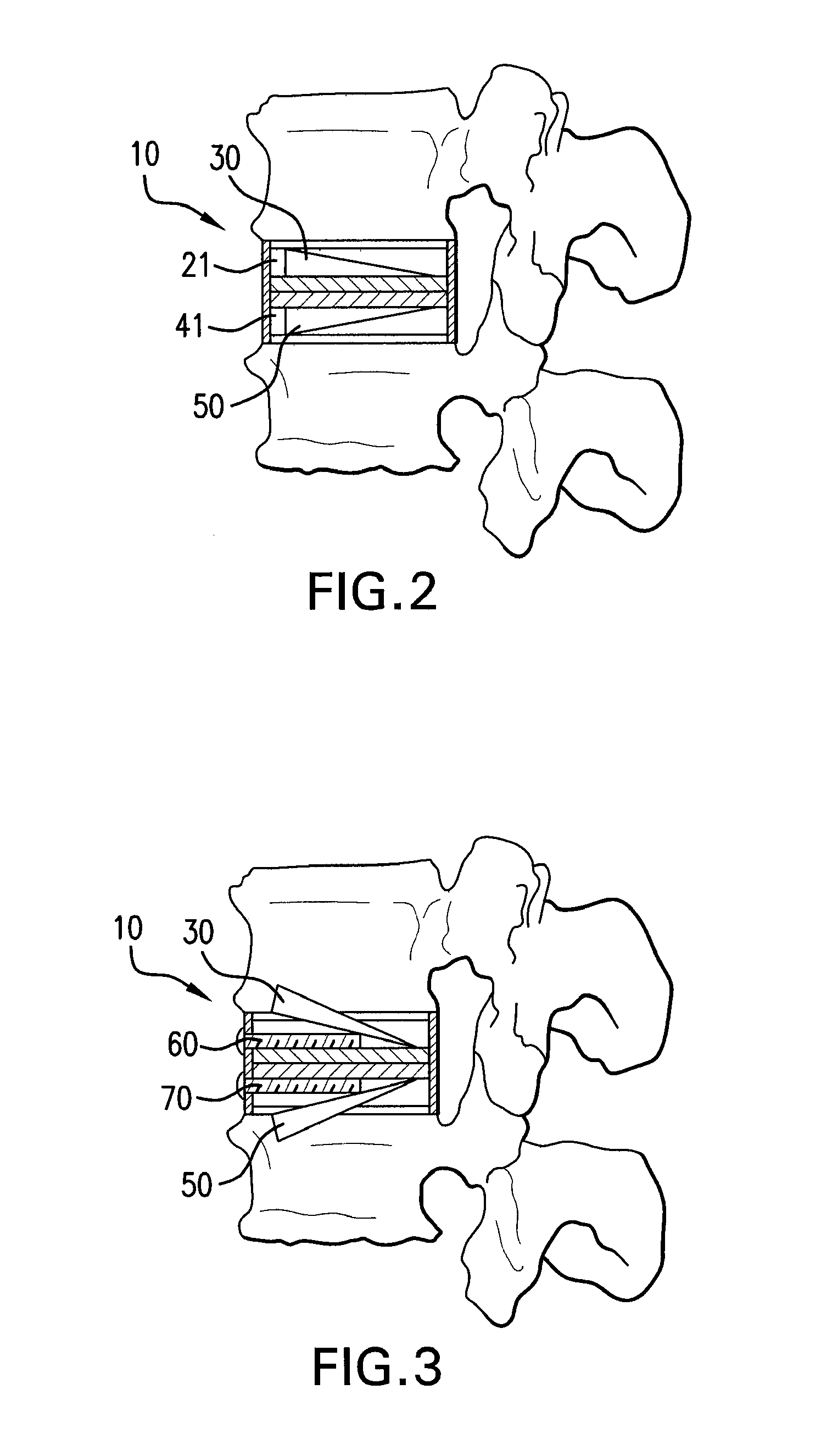
[0033] Referring to FIG. 1, in certain embodiments, the present invention provides an intervertebral disc prosthesis 10 comprising a first plate 20 and a second plate 40. First plate 20 has an upper surface 22, a lower surface 24, and side surfaces 25 to 28. As seen in FIG. 1, a first channel 21 extends at least partially through first plate 20. Upper surface 22 contains a slot 23, which is in fluid communication with first channel 21. Referring to FIG. 2, a first moveable anchor 30 is disposable in first channel 21. Similarly, referring back to FIG. 1, second plate 40 has a lower surface 42, an upper surface 44, and side surfaces 45 to 48. A second channel 41 extends at least partially through second plate 40. Lower surface 42 defines a slot 43 (not shown) in fluid communication with second channel 41. Similar to first plate 20, a second moveable anchor 50 is disposable in second channel 41, as shown in FIG. 2.

[0034] Referring to FIG. 2, in a non-deployed configuration, first and ...


PUM


Abstract

An intervertebral disc prosthesis is provided. The prosthesis includes a first and second plate containing modular anchors that are moveable from a radially un-extended position in a non-deployed configuration to a radially extended position in a deployed configuration. A method of replacing a natural intervertebral disc with a prosthetic disc is also provided.

Description

CROSS-REFERENCE TO RELATED APPLICATIONS [0001] The present application claims priority to U.S. Provisional Application No. 60 / 836,680 filed on Aug. 10, 2006 and U.S. Provisional Application No. 60 / 849,773 filed on Oct. 6, 2006, both of which are incorporated by reference herein.FIELD OF THE INVENTION [0002] The present invention relates to intervertebral disc prostheses and methods of replacing a natural intervertebral disc. BACKGROUND OF THE INVENTION [0003] The intervertebral disc provides a mechanical cushion between adjacent vertebral segments of the spinal column and also maintains the proper anatomical separation between two adjacent vertebrae. This separation is necessary for allowing both afferent and efferent nerves to respectively exit and enter the spinal column. In some instances, genetic or developmental irregularities, trauma, chronic stress or degenerative disease can result in spinal pathologies necessitating removal of an intervertebral disc. [0004] One option after...

Claims


Application Information

Patent Timeline
IPC IPC(8): A61F2/44A61B17/56
CPCA61F2002/30616A61F2002/4687A61F2002/30677A61F2002/30841A61F2002/443A61F2220/0025A61F2220/0033A61F2220/0091A61F2230/0065A61F2310/00017A61F2310/00023A61F2310/00029A61F2310/00203A61F2310/00239A61F2310/00293A61F2310/00317A61F2310/00407A61F2/30965A61F2/442A61F2/4425A61F2/4455A61F2/4611A61F2002/302A61F2002/30331A61F2002/30383A61F2002/30471A61F2002/30492A61F2002/305A61F2002/30563A61F2002/30579A61F2002/30604A61F2002/30649
Inventor DWYER, JAMES
Owner DWYER JAMES
Why Eureka
Try Eureka