
Battery pack and power receiving device

a power receiving device and battery pack technology, applied in the direction of batteries, safety/protection circuits, sustainable manufacturing/processing, etc., can solve the problems of high power consumption, discharged secondary batteries take a relatively large amount of time to recharge, and the capacity of existing second secondary batteries is insufficient to supply power to portable electronic devices

Inactive Publication Date: 2008-03-06
SAMSUNG SDI CO LTD
View PDF7 Cites 49 Cited by
  • Summary
  • Abstract
  • Description
  • Claims
  • Application Information

AI Technical Summary

Benefits of technology

[0010]Accordingly, aspects of the present invention provide a battery pack or a power receiving device that allow an external electric generator to be used without changing the existing portable electronic device.

Problems solved by technology

However, in the case of the portable electronic devices such as a notebook computer, a digital multimedia broadcasting (DMB) receiver, a wireless mobile Internet terminal, etc., the capacity of the existing second secondary battery is insufficient to supply power to the portable electronic devices because the portable electronic devices are generally used for a relatively long period of time and consume a relatively large amount of power.
Further, disadvantageously, the discharged secondary battery takes a relatively large amount of time to recharge.
For these reasons, there is a need for a separate power generator to supply power to the portable electronic device with a high power consumption.
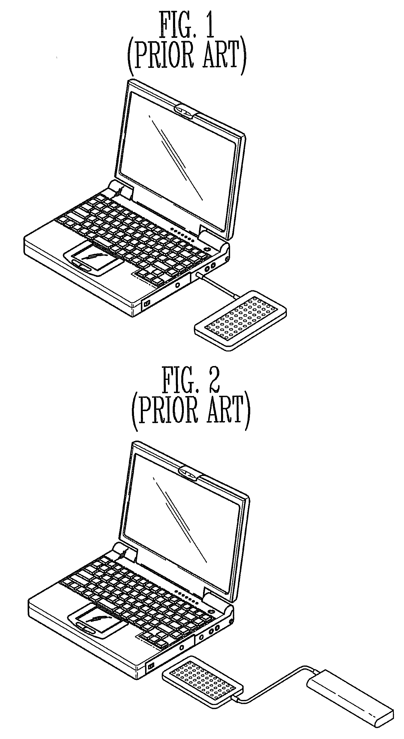
In the case shown in FIG. 1, there are problems in that the battery is not usable and an external power receiving device of the existing notebook computer must be changed.
In the case shown in FIG. 2, it is inconvenient for a user.
Even though the fuel cell is suitable for supplying the power to the portable electronic device, if the existing portable electronic device changes its structure, there is an economical disadvantage.
In this state, to mount the fuel cell onto the notebook computer, if the external casing, a circuit board, and the internal power receiving device of the notebook computer need to be changed, a manufacturer of the notebook computer must accept an excessive increase in the production cost.

Method used


Image

  • Battery pack and power receiving device
  • Battery pack and power receiving device
  • Battery pack and power receiving device

Examples


Embodiment Construction

[0028]Reference will now be made in detail to the present embodiments of the present invention, examples of which are illustrated in the accompanying drawings, wherein like reference numerals refer to the like elements throughout. The embodiments are described below in order to explain the present invention by referring to the figures.

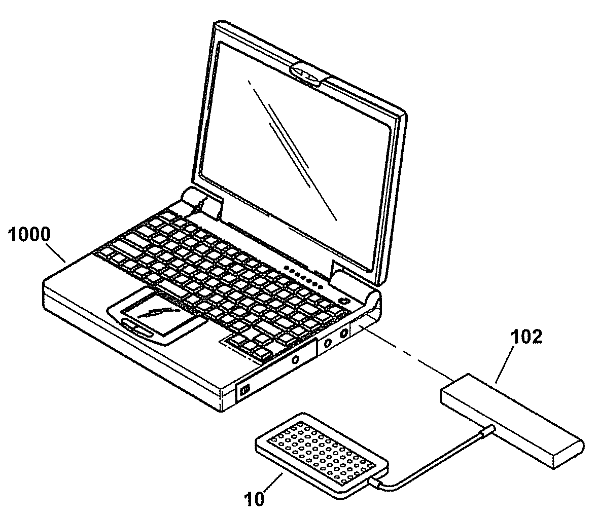
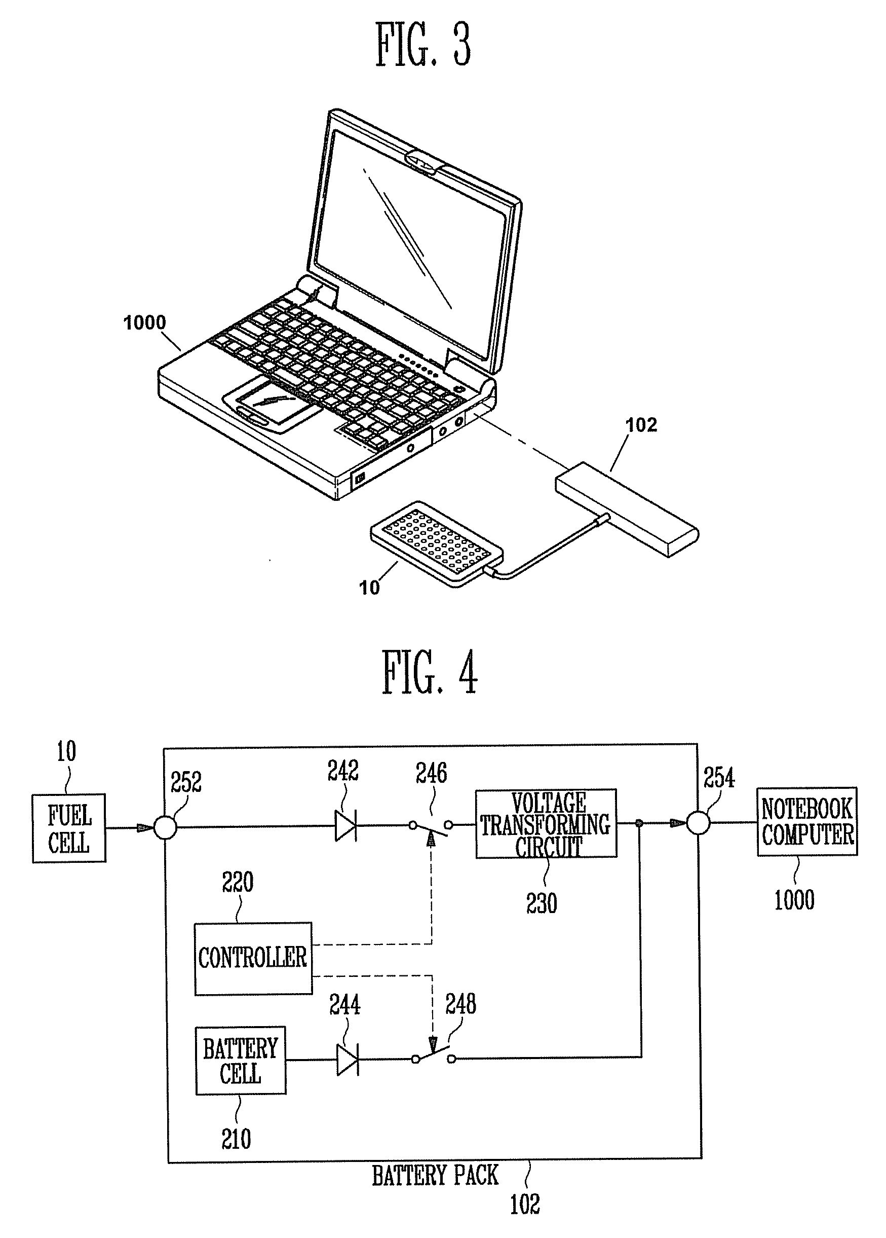
[0029]Hereinafter, a notebook computer is described as an example of a portable electronic device to which a battery pack is mounted, and a fuel cell is described as an example of an external power generator. However, it is understood that aspects of the present invention may be applied to any portable electronic device and external power generators.

[0030]A battery pack, according to an embodiment of the present invention, supplies power generated in an external power generator (such as a fuel cell or the like) and power discharged from a battery cell to a portable electronic device without changing a structure of a portable electronic device (such as ...


PUM

PropertyMeasurementUnit
output terminal voltageaaaaaaaaaa
poweraaaaaaaaaa

Abstract

A battery pack that is charged with power generated in an external power generator and supplies battery power to an external load in parallel with the external power generator, and a power receiving device of a portable electronic device that receives and supplies battery power to an external load in parallel with the external power generator, the battery pack including: a battery cell to discharge power based on a charged amount of electric charge; an external power input terminal to receive power from an external power generator; a power output terminal to supply power to an external load; and a voltage transforming circuit to transform voltage of the power received through the external power input terminal to transfer the transformed voltage to the power output terminal.

Description

CROSS-REFERENCE TO RELATED APPLICATION[0001]This application claims the benefit of Korean Patent Application No. 2006-84250, filed on Sep. 1, 2006 in the Korean Intellectual Property Office, the disclosure of which is incorporated herein by reference.BACKGROUND OF THE INVENTION[0002]1. Field of the Invention[0003]Aspects of the present invention relate to a battery pack that is charged with power generated in an external power generator and supplies discharge power to an external load in parallel with the external power generator.[0004]Further, aspects of the present invention relate to a power receiving device that is internally mounted onto a portable electronic device, charges an external battery with power generated in an external power generator, receives the power generated in the external power generator and power discharged from the external battery in parallel, and supplies the received power to the electronic device.[0005]2. Description of the Related Art[0006]Various port...

Claims


Application Information

Patent Timeline
Patent Type & Authority Applications(United States)
IPC IPC(8): H02J7/00H01M8/00
CPCH01M10/44H01M10/46H01M16/006Y02B90/18H02J7/0063H02J7/0068H02J7/34H01M2250/30Y02B90/10Y02E60/50Y02E60/10H02J7/007182Y02P70/50H02J7/0029H01M2220/30
Inventor KIM, DONG RAKSONG, IN SEOBPARK, JUNG KURNLEE, SANG CHEOLKIM, YOUNG JAE
Owner SAMSUNG SDI CO LTD
Learn More