
Device to indicate fuse capacity and electronic apparatus having the same

a technology of electronic apparatus and fuse capacity, which is applied in the direction of printed circuits, printed circuit details, printed circuit non-printed electric components associations, etc., can solve the problems of difficult installation process and long installation process, and achieve the effect of easy indication of fuse capacity

Inactive Publication Date: 2008-03-13
SAMSUNG ELECTRONICS CO LTD
View PDF6 Cites 1 Cited by
  • Summary
  • Abstract
  • Description
  • Claims
  • Application Information

AI Technical Summary

Benefits of technology

[0014]The present general inventive concept provides a device to easily indicate a fuse capacity in an electric apparatus which uses various fuses having different capacities on a PCB.
[0015]The present general inventive concept provides a device to indicate a fuse capacity which can easily indicate a capacity of a fuse mounted on a PCB according to a selective mounting position of the fuse at PCB patterns without an additional indicating process by modifying the PCB patterns on the PCB.

Problems solved by technology

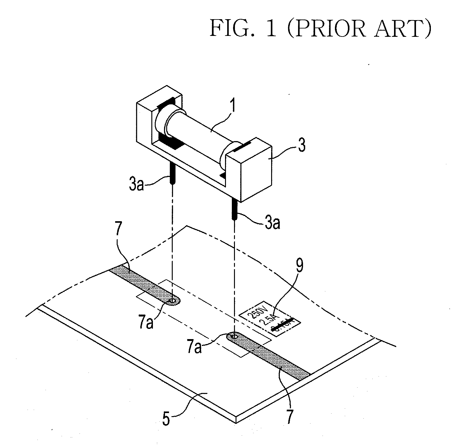
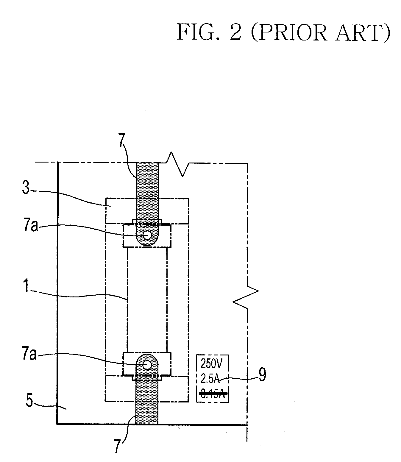
However, because the deleting work of the non-used fuse capacity mark should be additionally performed after the fuse block 3 with the fuse 1 is mounted to the PCB pattern hole 7a, it takes much time for installation.
Further, when the fuse capacity mark in use is deleted by mistake, it may make the installing process very troublesome.

Method used


Image

  • Device to indicate fuse capacity and electronic apparatus having the same
  • Device to indicate fuse capacity and electronic apparatus having the same
  • Device to indicate fuse capacity and electronic apparatus having the same

Examples


Embodiment Construction

[0036]Reference will now be made in detail to exemplary embodiments of the present general inventive concept, examples of which are illustrated in the accompanying drawings, wherein like reference numerals refer to like elements throughout. The embodiments are described below to explain the present general inventive concept by referring to the figures.

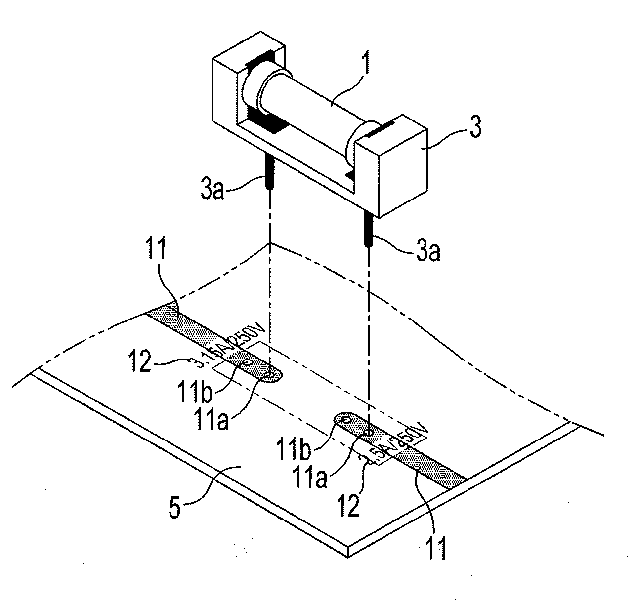
[0037]FIG. 3 is a schematic view illustrating a device to indicate a fuse capacity of a fuse 1 which is mounted on a PCB 5, according to an embodiment of the present general inventive concept.

[0038]Referring to FIG. 3, first and second PCB patterns 11 are formed on the PCB 5, and lower and upper PCB pattern holes 11a and 11b are formed at both the first and second PCB patterns 11. The lower and upper PCB pattern holes 11a and 11b are arranged in a longitudinal direction of the PCB patterns 11, and lead members 3a of a fuse block 3 are inserted into the PCB pattern holes 11a and 11b. Fuse capacity indicating parts 12, on which two diffe...


PUM


Abstract

A device to indicate a fuse capacity includes a fuse, a printed circuit board (PCB), on which the fuse is mounted, and a capacity indicating part to expose one of different fuse capacities, corresponding to the fuse mounted on the PCB, and to shield other fuse capacities. Accordingly, the device can easily indicate the fuse capacity in electric apparatus which uses various fuses having different capacities on the PCB.

Description

CROSS-REFERENCE TO RELATED APPLICATIONS[0001]This application claims priority under 35 U.S.C. §119(a) from Korean Patent Application No. 2006-0087537, filed on Sep. 11, 2006 in the Korean Intellectual Property Office, the disclosure of which is incorporated herein in its entirety by reference.BACKGROUND OF THE INVENTION[0002]1. Field of the Invention[0003]The present general inventive concept relates to a device to indicate a fuse capacity, and more particularly to a device to indicate a fuse capacity of two or more fuse capacities on the same PCB (Printed Circuit Board), and an electronic apparatus having the same.[0004]2. Description of the Related Art[0005]Generally, a conventional air conditioner is an apparatus for cooling or heating an indoor room, which comprises an indoor unit, an outdoor unit, and a refrigerant circulating the indoor and outdoor units. When the liquid state refrigerant is evaporated, the refrigerant absorbs environmental heat. When the gas state refrigerant...

Claims


Application Information

Patent Timeline
Patent Type & Authority Applications(United States)
IPC IPC(8): H01H85/04
CPCH01H85/202H01H85/34H01H2085/2085H05K2201/10181H05K1/18H05K2201/09936H05K2201/09954H05K1/0266H01H85/04H01H85/165H01H85/30
Inventor KIM, YOUNG SEOK
Owner SAMSUNG ELECTRONICS CO LTD
Learn More