Brake carrier

a technology of brake carrier and brake, which is applied in the direction of brake type, axially engaging brake, braking element, etc., can solve the problems of increasing the overall weight of the axle and the brake without a corresponding increase in strength, and it is increasingly difficult to produce a brake carrier that is sufficiently strong, light and compact to transmit this load

Active Publication Date: 2008-03-20
MERITOR HEAVY VEHICLE BRAKING SYST (UK) LTD
View PDF17 Cites 41 Cited by
  • Summary
  • Abstract
  • Description
  • Claims
  • Application Information

AI Technical Summary

Problems solved by technology

Disadvantageously, this arrangement adds to the overall weight of the axle and brake without a corresponding increase in strength, and results in additional fixing bolts being used in locations where they are not readily accessible when the axle is installed on a vehicle.
Furthermore, it has become apparent in recent years that as clamp forces, and hence frictional forces, in heavy vehicle brakes rise, it is increasingly difficult to produce a brake carrier that is sufficiently strong, light and compact to transmit this load to the vehicle axle, particularly on the actuating side thereof.

Method used


Image

  • Brake carrier
  • Brake carrier
  • Brake carrier

Examples


first embodiment

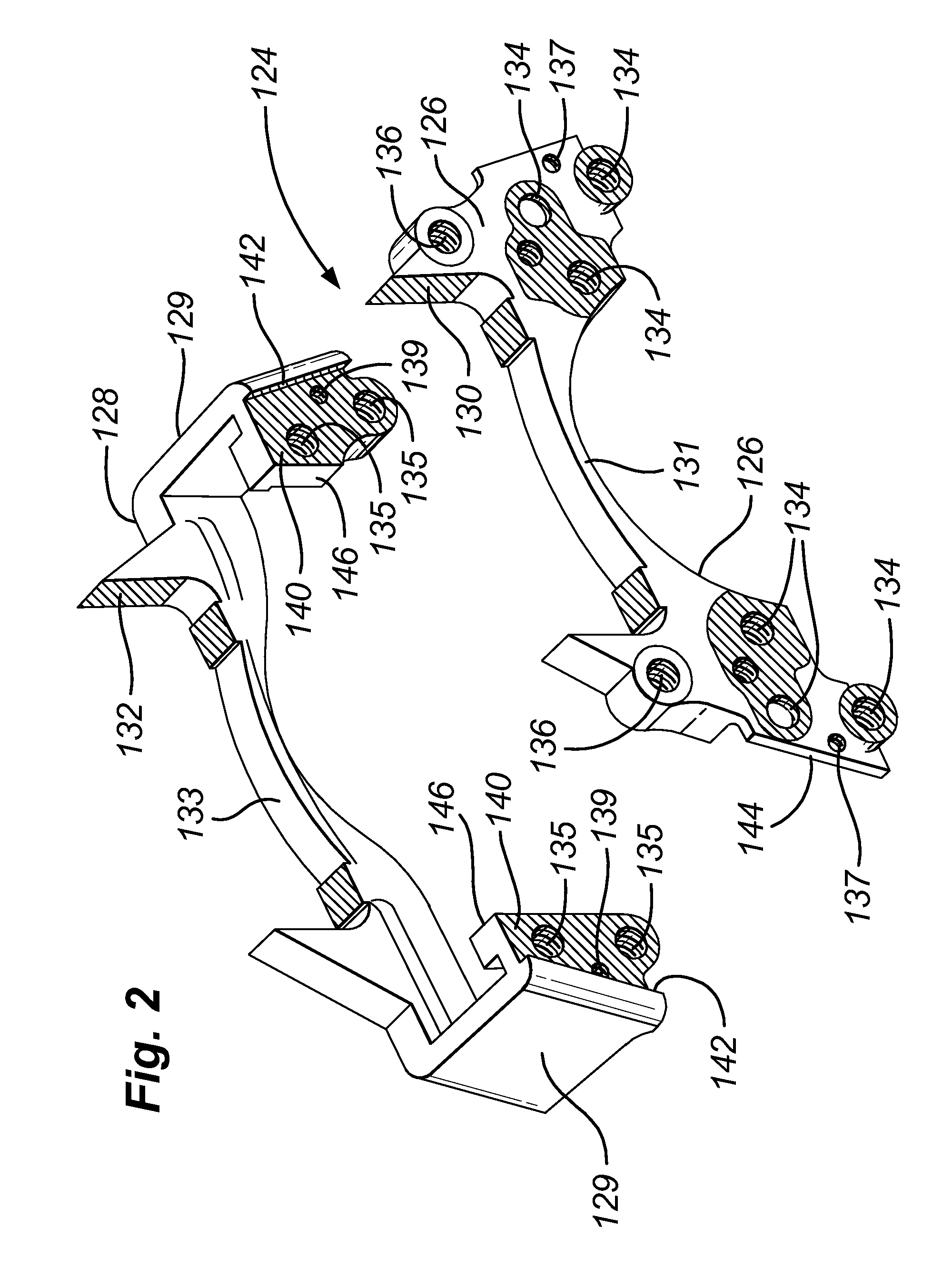
[0029] Referring to FIGS. 2 and 3, a carrier 124 according to the present invention is shown. Like parts has been labelled by like numerals with the addition of the prefix “1”. Only those differences with respect to the prior art are discussed in great depth.

[0030] The carrier 124 includes an actuating side portion 126 and a separate reaction side portion 128. The actuating side portion 126 includes a recess 130 for accommodating an actuating side brake pad and threaded bores 136 for caliper guide pins (not shown). The reaction side portion 128 includes a recess 132 for a reaction side brake pad (not shown) and arms 129.

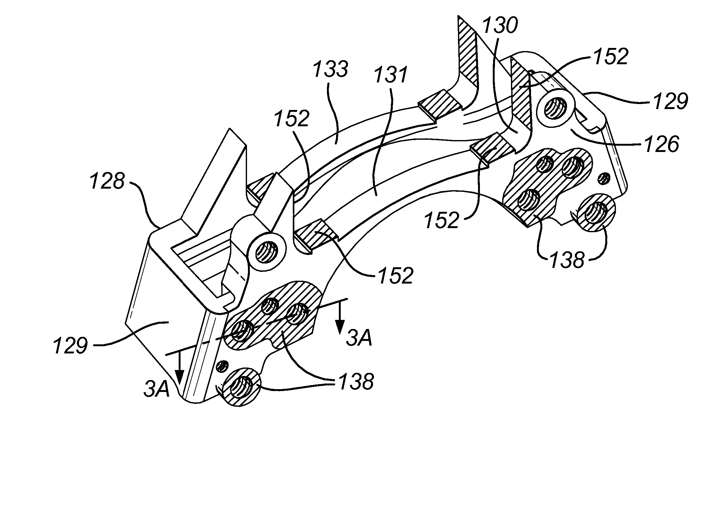
[0031] With reference to FIG. 3A, the reaction side portion 128 includes a transverse mating face 140 arranged to contact a corresponding face 150 of the actuating side portion 126. The reaction side portion 128 further includes circumferential faces 142 and 146 that contact corresponding faces 144 and 148 of the actuating side portion 126. As a result, when the act...

second embodiment

[0035] Turning now to FIG. 5, the present invention is illustrated, with similar parts denoted by the same reference numerals, with the addition of the prefix “2”.

[0036] Again, only differences with respect to the prior art and first embodiment are discussed in great depth.

[0037] A carrier 224 of the second embodiment includes a reaction side portion 228 similar to that of the first embodiment, except that it omits the circumferential mating faces and includes a single transverse face 240.

[0038] An actuating side portion 226 of the carrier 224 is however integrally formed with the adapter plate, such that the actuating side portion 226 of the carrier 224 is secured directly to the intermediate bracket 12 by bolts (not shown) through the bores 14 of the intermediate bracket 12 and bores 218 of the carrier 224. The bolts transmit the circumferential load from the reaction side brake pad to the actuating side portion 226 of the carrier 224 due to the omission of circumferential matin...


PUM


Abstract

A brake carrier for a heavy vehicle disc brake includes an actuating side carrier portion including a support for an actuating side brake pad having a first material having a first property. The brake carrier also includes a separate reaction side carrier portion having a support for a reaction side brake pad for securement to the actuating side carrier portion. The actuating side carrier portion includes a first material having a first property, and the reaction side carrier portion includes a second material having a second property, wherein the second property differs from the first property.

Description

REFERENCE TO RELATED APPLICATIONS [0001] This application claims priority to United Kingdom Patent Application No. GB 0618416.2 filed on Sep. 19, 2006. BACKGROUND OF THE INVENTION [0002] The present invention relates to a brake carrier, in particular, a carrier for a heavy vehicle disc brake. [0003] Heavy vehicles, such as rigid body trucks, tractor and semi-trailer trucks, and buses may be braked on their steered and unsteered axles, driven and undriven axles by either drum brakes or disc brakes. Drum brake linings and their associated actuation mechanisms are supported on fixed axles or the steering knuckles of steered axles by a bracket welded directly to the axle, which has all the required mounting parts, or via an intermediate bracket welded to the axle with a number of mounting holes for the bolts of a separate support for the linings and actuation mechanism. [0004] In the latter case, it is known to provide an adapter plate that is bolted to this intermediate bracket in orde...

Claims


Application Information

Patent Timeline
Patent Type & Authority Applications(United States)
IPC IPC(8): F16D65/095
CPCF16D2055/0008F16D55/00F16D65/0056
Inventor THOMAS, PAULJACKSON, JONATHAN LESLIE CHRISTOPHER
Owner MERITOR HEAVY VEHICLE BRAKING SYST (UK) LTD
Why Eureka
Try Eureka