Double Sided Rack Manipulator Jaw Actuator System

a manipulator and actuator technology, applied in the direction of manipulators, gripping heads, load-engaging elements, etc., can solve the problems of c-bushings being bound up on the t-plate, jaw jamming, t-plate and/or associated bolt damage,

Inactive Publication Date: 2008-03-27
OCEANEERING INTERNATIONAL
View PDF16 Cites 55 Cited by
  • Summary
  • Abstract
  • Description
  • Claims
  • Application Information

AI Technical Summary

Problems solved by technology

In prior art systems comprising C bushings and a T plate, the force of an uneven load on the jaws can cause the T-plate to be pried away from the piston shaft, causing the bolt that secures it to bend, thereby...

Method used


Image

  • Double Sided Rack Manipulator Jaw Actuator System
  • Double Sided Rack Manipulator Jaw Actuator System
  • Double Sided Rack Manipulator Jaw Actuator System

Examples


Embodiment Construction

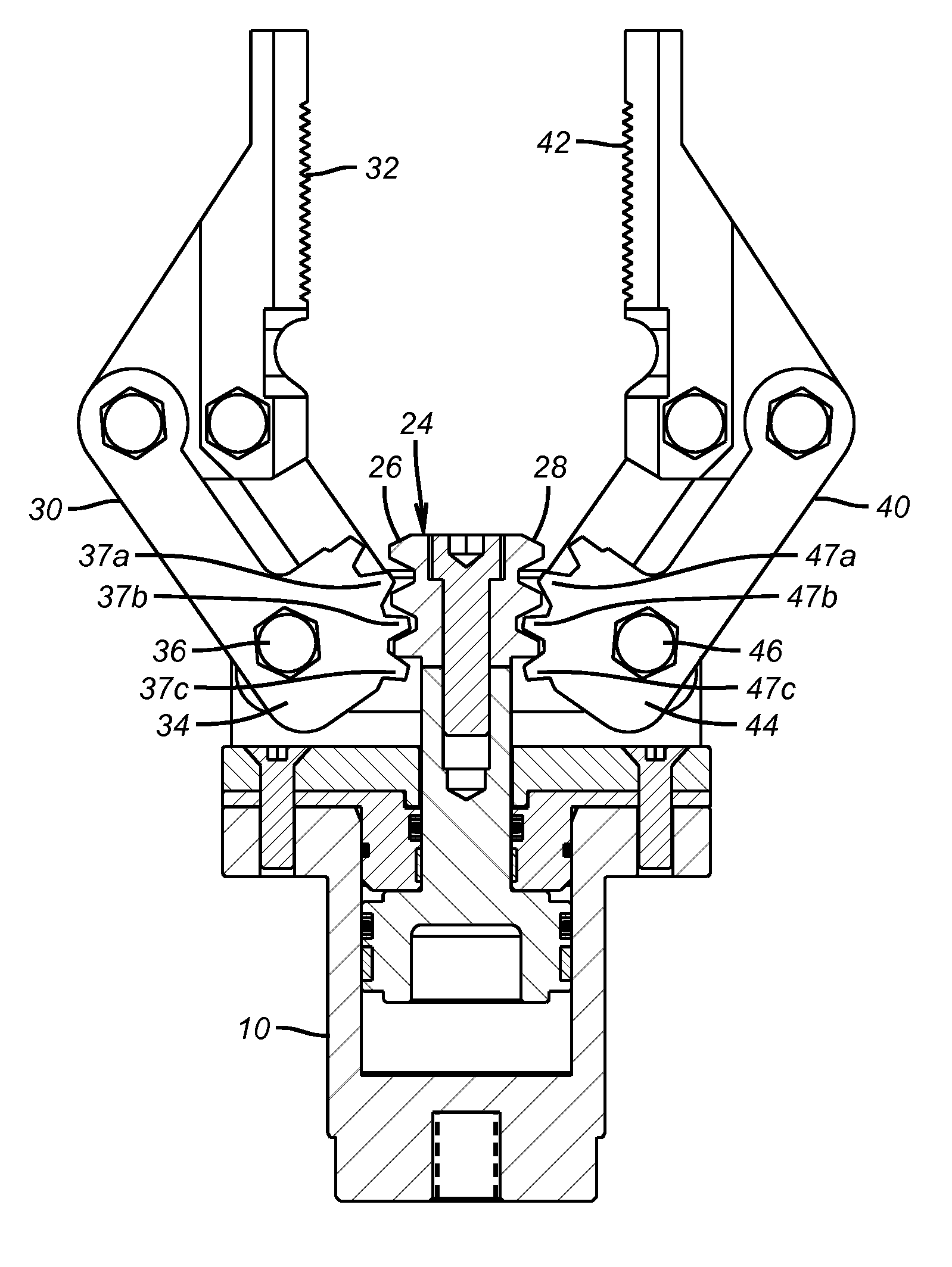
[0011]A first preferred apparatus embodiment of the invention is directed to a manipulator jaw and actuator system. It comprises a piston housing 10 comprising a piston chamber 12, a fluid inlet 14, and a fluid outlet 16, as shown in FIG. 2. In one preferred embodiment, the piston housing is cylindrical.

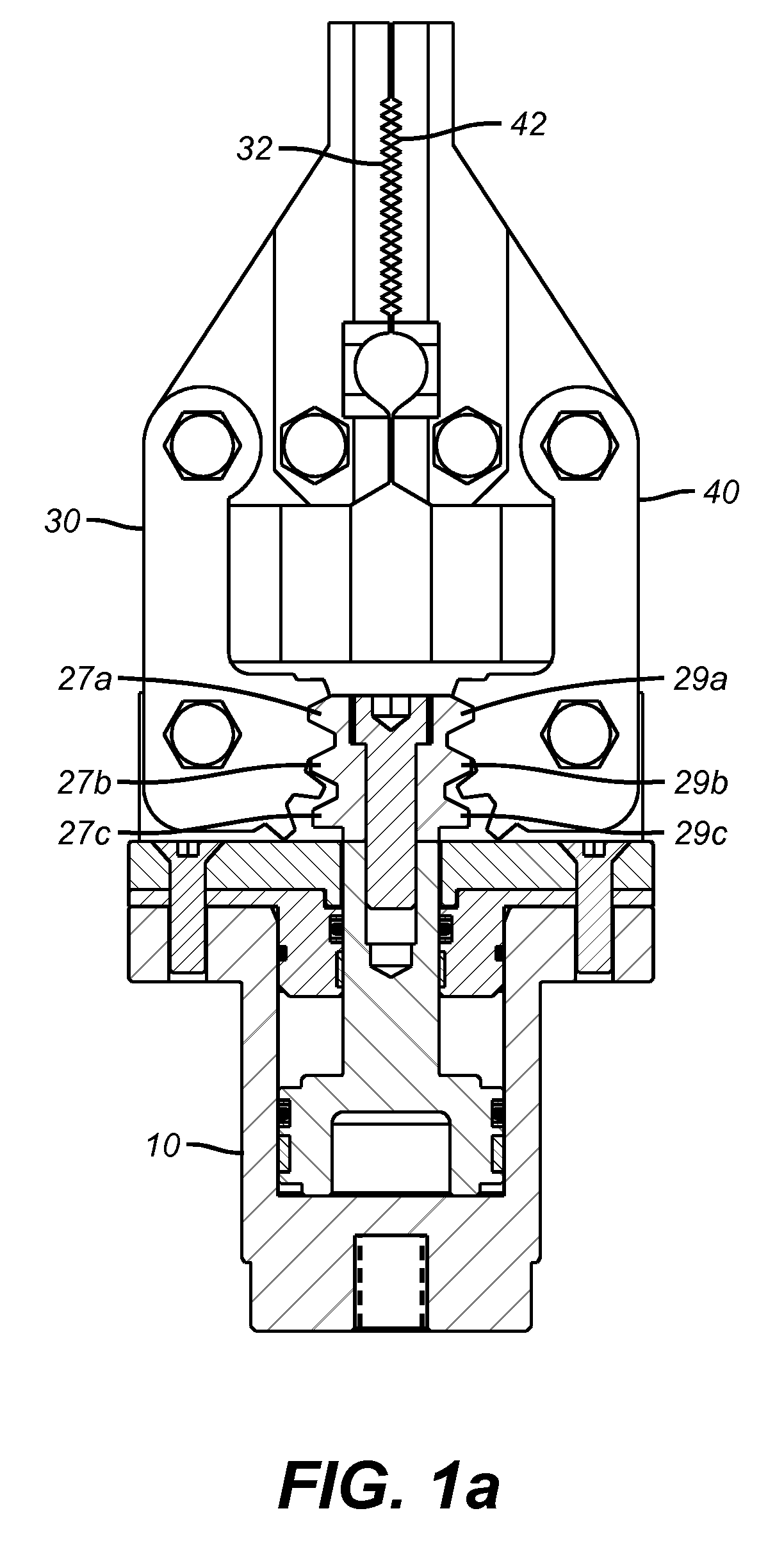
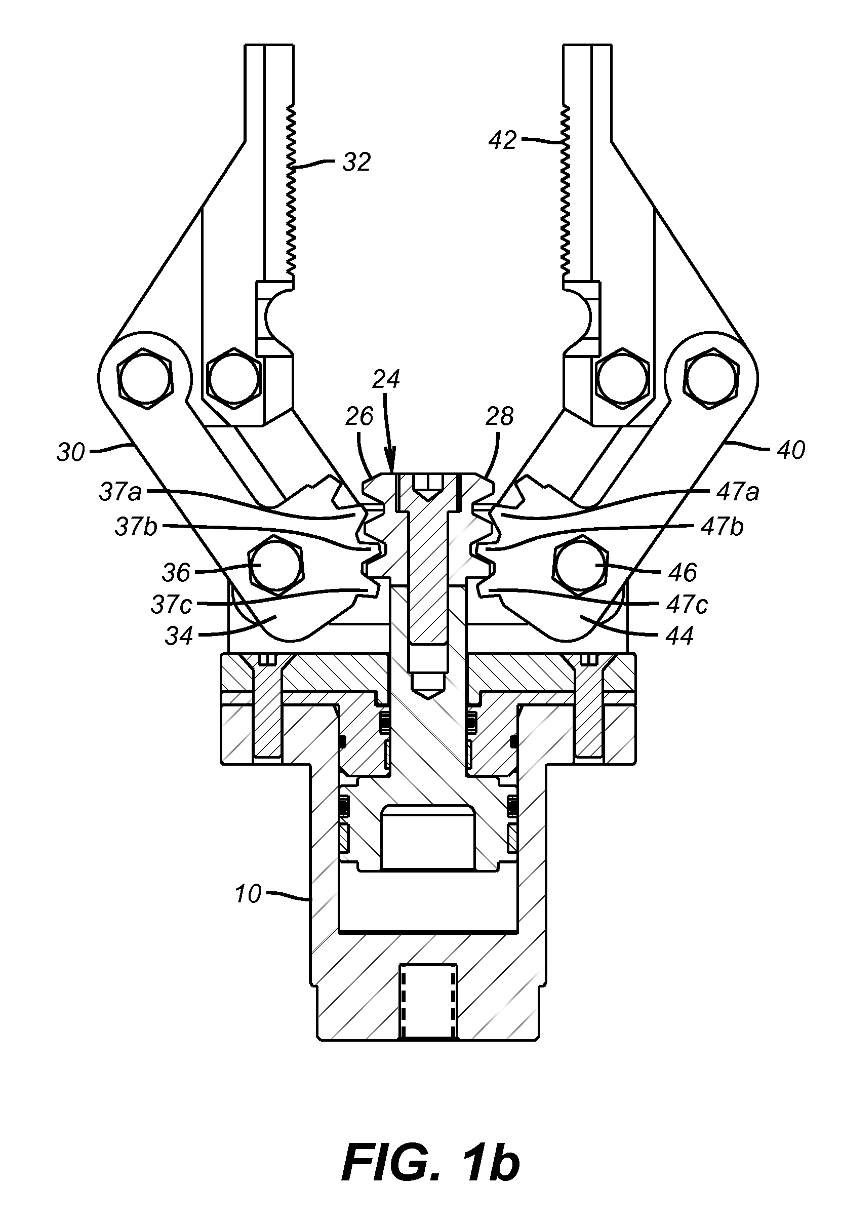
[0012]This apparatus embodiment further comprises a piston 18 having a lower region 20 slideably mounted in the piston chamber and an upper region 22 extending beyond the piston housing, as shown in FIG. 2, The piston is mounted in the housing such that the piston can reciprocate longitudinally from a final extended position, as shown in FIG. 1b, to a final retracted position, as shown in FIG. 1a, and from a final retracted position to a final extended position. The directions of this longitudinal reciprocation is denoted by arrow Z in FIG. 2.

[0013]This apparatus embodiment further comprises a toothed rack 24 mounted on the upper region of said piston such that the rack moves with th...


PUM


Abstract

This invention is directed to a system for actuating manipulator jaws. This system employs a double sided rack, each side of which engages a pinion at a first end of a rotatably mounted lever. The second end of each lever comprises a jaw region. The present invention may be used with subsea manipulators mounted on remotely operated vehicles (“ROV's”).

Description

CROSS REFERENCE TO RELATED APPLICATION[0001]This application claims the benefit of Provisional Application Ser. No. 60 / 847,625, filed on Sep. 27, 2006.FIELD OF THE INVENTION[0002]This invention is directed to a system for actuating manipulator jaws. This system employs a double sided rack, each side of which engages a pinion at a first end of a rotatably mounted lever. The second end of each lever comprises a jaw region. The present invention may be used with subsea manipulators mounted on remotely operated vehicles (“ROV's”).BACKGROUND OF THE INVENTION[0003]Prior art systems for actuating manipulator jaws comprise “C” shaped bushings, herein referred to as a “C bushing” that engages a T plate attached to a reciprocating piston. In such prior systems, as the piston extends, the contact between the C bushings and the t plate is steadily reduced. In such prior art systems, as the manipulator is used and the jaws are clamped around whatever is being pulled, moved, or picked up, this in...

Claims


Application Information

Patent Timeline
IPC IPC(8): B25J15/08
CPCB25J15/0213
Inventor HOLTZ, TODD GRANGER
Owner OCEANEERING INTERNATIONAL
Why Eureka
Try Eureka