Infrared clinical thermometer

a thermometer and infrared technology, applied in the field of infrared clinical thermometers, can solve problems such as inconvenient measurement comparison

Inactive Publication Date: 2008-03-27
RADIANT INNOVATION INC
View PDF7 Cites 2 Cited by
  • Summary
  • Abstract
  • Description
  • Claims
  • Application Information

AI Technical Summary

Benefits of technology

[0008]One objective of the present invention is to provide an infrared clinical thermometer, wherein the current and former measurement results can be simultaneously presented on a display, and whereby the user can conveniently compare the current measurement result with the former measurement result.

Problems solved by technology

Nevertheless, the conventional infrared clinical thermometer can present only one measured temperature each time, which inconveniences the comparison of measurement results.

Method used


Image

  • Infrared clinical thermometer
  • Infrared clinical thermometer
  • Infrared clinical thermometer

Examples


Embodiment Construction

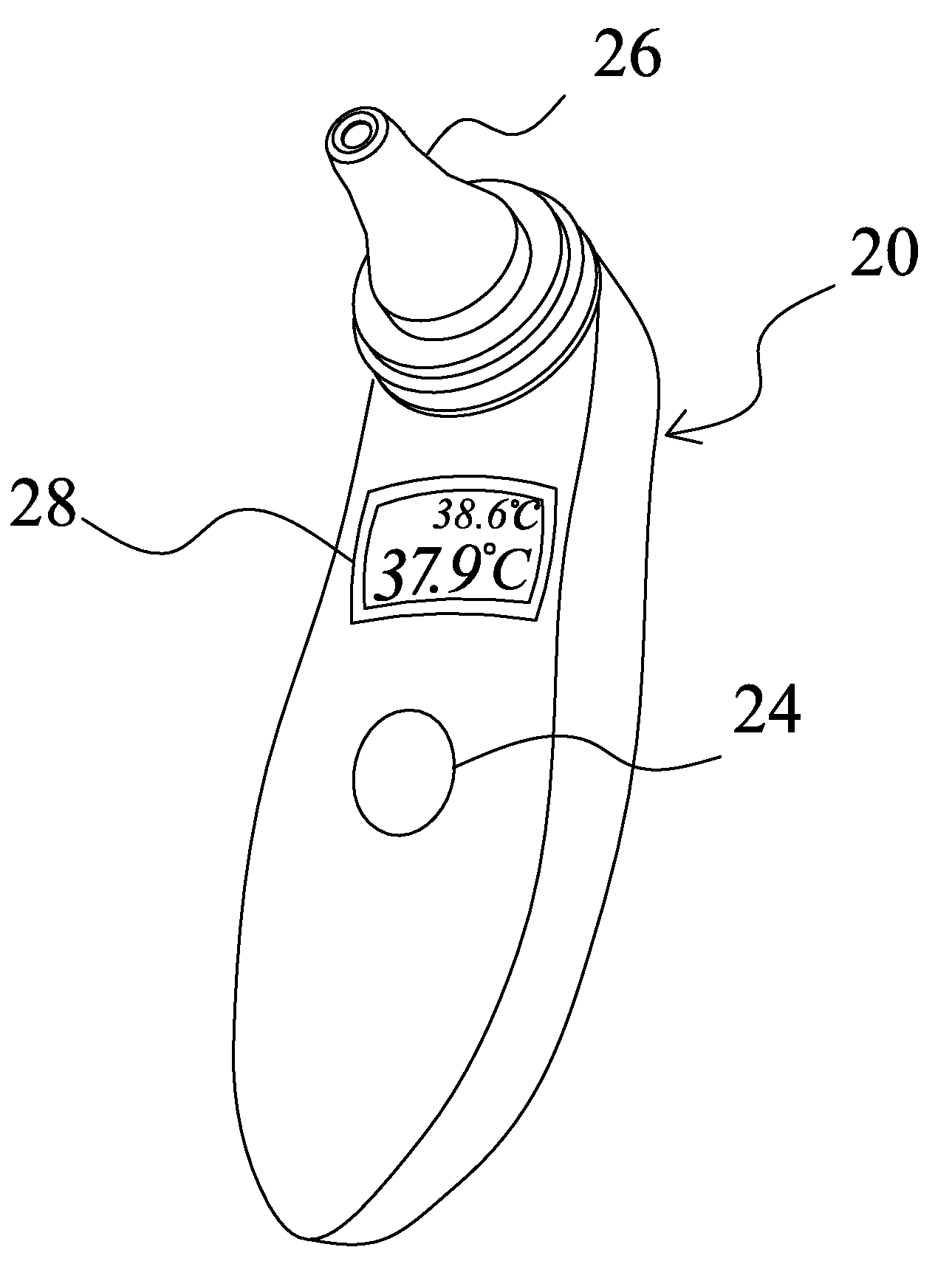
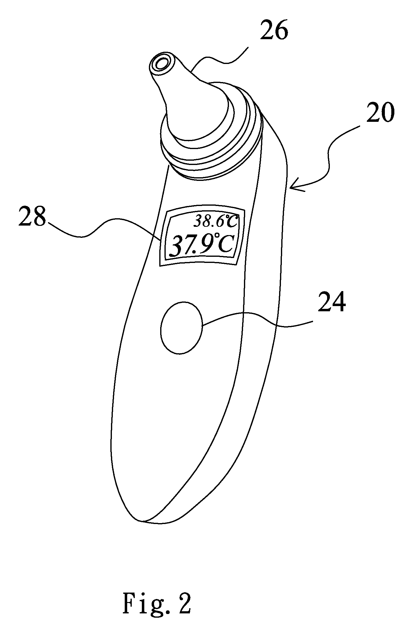
[0015]The present invention pertains to an infrared clinical thermometer, such as an infrared ear thermometer or an infrared forehead thermometer, wherein the current and former measurement results can be simultaneously presented on a display. Below, the preferred embodiment that the present invention is applied to an ear thermometer is used to demonstrate the technical contents, characteristics and accomplishments of the present invention.

[0016]Refer to FIG. 2 and FIG. 3 respectively a diagram schematically showing an ear thermometer according to the present invention and a block diagram showing the circuit of an ear thermometer according to the present invention. The ear thermometer of the present invention comprises a thermometer casing 20; a display unit 28 on the casing 20; a button unit 24 on the casing 20; a temperature sensing unit 26 at one end of the casing 10; and a control circuit 22 (not shown in the drawings) inside the casing 10 and coupled to the display unit 28, the...


PUM


Abstract

The present invention discloses an infrared clinical thermometer, which comprises a casing, a temperature-sensing unit at one end of the casing, and a display unit on the casing, wherein the current and former measurement results are simultaneously presented on the display unit to facilitate the comparison of the measurement results.

Description

BACKGROUND OF THE INVENTION[0001]1. Field of the Invention[0002]The present invention relates to an infrared clinical thermometer, particularly to an infrared clinical thermometer, wherein the current and former temperature measurement results can be simultaneously presented on a same picture.[0003]2. Description of the Related Art[0004]With the advance of science and technology, the clinical thermometer has evolved from the traditional mercury thermometer to the infrared thermometer, such as the infrared ear thermometer or the infrared forehead thermometer. The infrared clinical thermometer has been very popular because it can fast obtain a body temperature within seconds.[0005]Refer to FIG. 1 a diagram schematically showing a conventional infrared clinical thermometer. The conventional infrared clinical thermometer has a casing 10, and a probe 12 is arranged at one end of the casing 10. The probe 12 has an infrared temperature sensor to measure body temperature. The measurement re...

Claims


Application Information

Patent Timeline
Patent Type & Authority Applications(United States)
IPC IPC(8): G01J5/00G01J5/04
CPCG01J5/0022G01J5/0025G01J5/02G01J5/12G01J5/04G01J5/049G01J5/025
Inventor WENG, VINCENTLIAO, JASON
Owner RADIANT INNOVATION INC
Why Eureka
Try Eureka