
Method and system for leakage status evaluation and leaks location of solid waste land disposal facility

a technology for solid waste land and leakage status, applied in the direction of fluid tightness measurement, structural/machine measurement, instruments, etc., can solve the problems of only suitable dipole method and risk of leakage, and achieve the effect of interfering with the site background

Pending Publication Date: 2022-01-13
CHINESE RES ACAD OF ENVIRONMENTAL SCI
View PDF3 Cites 0 Cited by
  • Summary
  • Abstract
  • Description
  • Claims
  • Application Information

AI Technical Summary

Benefits of technology

The present invention has the following benefits: 1. It quantitatively evaluates leakage statuses in different regions of the country, making it convenient to compare. 2. It eliminates interference from the site background by normalizing conductivity differences. 4. It effectively reduces the number of electrodes required to be arranged in place, while ensuring accuracy of the maximum current position.

Problems solved by technology

A solid waste land disposal facility is a major groundwater pollution source, and the leachate produced in the solid waste land disposal process contains high concentrations of organic and inorganic pollutants, which have great consequences once entering soil and groundwater environments.
An artificial leakage prevention system is an important engineering barrier to prevent and control the groundwater pollution, but the leakage prevention system may be damaged, and there is still a risk of leakage after the leakage prevention system is put into operation.
The dipole method is only suitable for the situation that the total thickness of a medium (garbage and discharge guiding cobbles) above the impermeable layer is not more than 60 cm.

Method used


Image

  • Method and system for leakage status evaluation and leaks location of solid waste land disposal facility
  • Method and system for leakage status evaluation and leaks location of solid waste land disposal facility
  • Method and system for leakage status evaluation and leaks location of solid waste land disposal facility

Examples


embodiment 1

[0036]According to the embodiment of the present invention, a method for leakage status evaluation and leaks location of a solid waste land disposal facility is provided. The method includes the following steps:

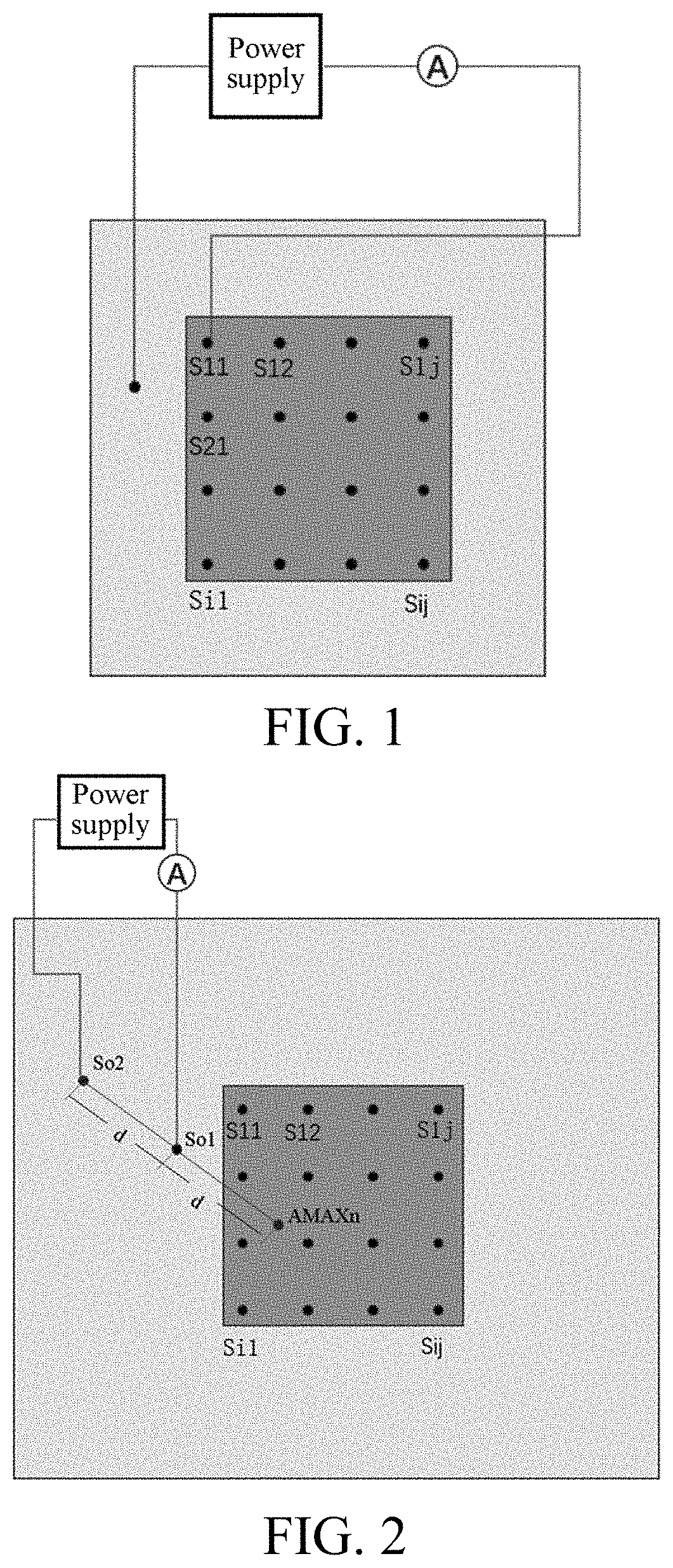
[0037]Step S101: An off-site emitting electrode is arranged for the solid waste land disposal facility, and a plurality of intra-site receiving electrodes are arranged on a solid waste pile surface in a grid shape.

[0038]Specifically, one off-site emitting electrode is arranged for the solid waste land disposal facility, and a plurality of intra-site (solid waste pile surface) receiving electrodes are arranged in a grid shape. In the present embodiment, the grid-shaped distribution of the intra-site electrodes is

[S1⁢1S1⁢2…S1⁢jS2⁢1S2⁢2…S2⁢j⋮⋮⋮⋮Si⁢⁢1Si⁢⁢2…Sij].

Of course, a person skilled in the art would be able to select the number and arrangement of electrodes according to practical requirements.

[0039]Step S102: A power supply is selected to supply power, a current value betwe...

embodiment 2

[0053]According to the embodiment of the present invention, a system for leakage status evaluation and leaks location of a solid waste land disposal facility is further provided. The system includes the following components:

[0054](1) An off-site emitting electrode, arranged for the solid waste land disposal facility, and a plurality of intra-site receiving electrodes, arranged on a solid waste pile surface according to a grid-shaped structure.

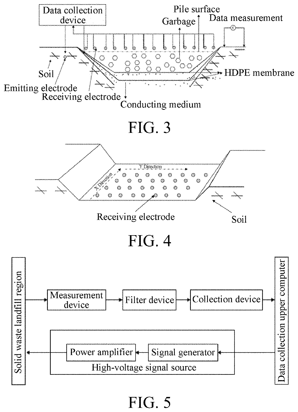
[0055]Specifically, referring to FIG. 3, in the early days, solid waste was landfilled without laying sensors at the bottom of a reservoir, and existing methods of determining a leakage position through sensors at the bottom of the reservoir were ineffective when leakages occurred at these sites. In the present embodiment, a plurality of receiving electrodes are laid on a solid waste pile surface according to a set rule. FIG. 4 shows a schematic diagram of arrangement of receiving electrodes. A high-voltage excitation signal is input to a solid...

embodiment 3

[0066]In one or more implementations, a terminal device is provided, including a server. The server includes a memory, a processor, and a computer program stored in the memory and capable of being run on the processor, and the processor, when executing the program, implements the method and the system for leakage status evaluation and leaks location of a solid waste land disposal facility in Embodiment 1. For brevity, details are not described herein again.

[0067]It should be understood that in this embodiment, the processor may be a central processing unit (CPU); or the processor may be another general purpose processor, a digital signal processor (DSP), an application-specific integrated circuit (ASIC), a field programmable gate array (FPGA) or another programmable logical device, a discrete gate or a transistor logical device, a discrete hardware component, or the like. The general-purpose processor may be a microprocessor, or the processor may be any conventional processor and th...


PUM


Abstract

A method and system for leakage status evaluation and leaks location of a solid waste land disposal facility. The method includes: arranging an off-site emitting electrode for the solid waste land disposal facility, and arranging a plurality of intra-site receiving electrodes on a solid waste pile surface in a grid shape; selecting a power supply to collect a current value between the off-site emitting electrode and each of the intra-site receiving electrodes respectively, and determining a maximum current value point Mn of the solid waste pile surface and a maximum current value An; selecting an off-site point So2, and measuring a current value between the off-site emitting electrode and the point So2 as a reference current Ab under the same power supply condition; and determining a leakage status of the solid waste land disposal facility based on a ratio of the maximum current value An to the reference current Ab.

Description

BACKGROUNDTechnical Field[0001]The present invention relates to the technical field of harmless disposal of solid waste, and in particular, to a method and a system for leakage status evaluation and leaks location of a solid waste land disposal facility.Related Art[0002]The description in this section merely provides background information related to the present invention and does not necessarily constitute the prior art.[0003]Land disposal facilities are the main means of harmless disposal of solid waste. The number of land disposal facilities is large, and is still growing continuously at present. A solid waste land disposal facility is a major groundwater pollution source, and the leachate produced in the solid waste land disposal process contains high concentrations of organic and inorganic pollutants, which have great consequences once entering soil and groundwater environments. An artificial leakage prevention system is an important engineering barrier to prevent and control t...

Claims


Application Information

Patent Timeline
Patent Type & Authority Applications(United States)
IPC IPC(8): G01M3/18B09B5/00G01M3/40
CPCG01M3/18G01M3/40B09B5/00B09B1/00G01M99/00G01V3/12G01V3/083G01V3/28G01S13/885G01S13/88G01S13/0209
Inventor XU, YALIU, YUQIANGLIU, JINGCAIYAO, GUANGYUANZHENG, KAIDANAI, CHANGXINDONG, LUHUANG, QIFEI
Owner CHINESE RES ACAD OF ENVIRONMENTAL SCI
Learn More