Camera system with side-by-side image display

a camera system and image display technology, applied in the field of camera systems, can solve the problems of inconvenient camera system for a beginner unaccustomed to photography, inability to compare images, and conventional camera system lacked convenience in comparing images, so as to improve convenience for users

Active Publication Date: 2012-06-12
PANASONIC CORP
View PDF17 Cites 0 Cited by
  • Summary
  • Abstract
  • Description
  • Claims
  • Application Information

AI Technical Summary

Benefits of technology

[0012]The present invention provides a camera system which is designed and configured to improve convenience for the user by allowing a plurality of images to be displayed side by side.
[0015]Here, when the plurality of images displayed in the first and second display regions are compared using the first image as a reference, the first image serving as the reference is successively updated to the most recent image acquired under a specific photography condition. As a result, when the user changes the frame, or when the subject moves, for example, two successively updated images with substantially the same composition can be compared. That is, this camera system is more convenient in comparing images.

Problems solved by technology

Therefore, in the case of a digital camera, with the above-mentioned system, a monitor photography mode, in which the user uses the liquid crystal monitor to view the subject, cannot be achieved, and a camera system such as this is inconvenient for a beginner unaccustomed to photography.
However, if the user changes the framing, or if the subject moves, when the two images are compared, the composition can be quite different between the reference image acquired ahead of time and the comparative image serving as a live image, so that the images cannot be compared.
Thus, a conventional camera system lacked convenience in comparing images in some situations.

Method used


Image

  • Camera system with side-by-side image display
  • Camera system with side-by-side image display
  • Camera system with side-by-side image display

Examples


first embodiment

[0046]Embodiments of the present invention will now be described through reference to the drawings.

[0047]1: Overall Configuration of Camera System

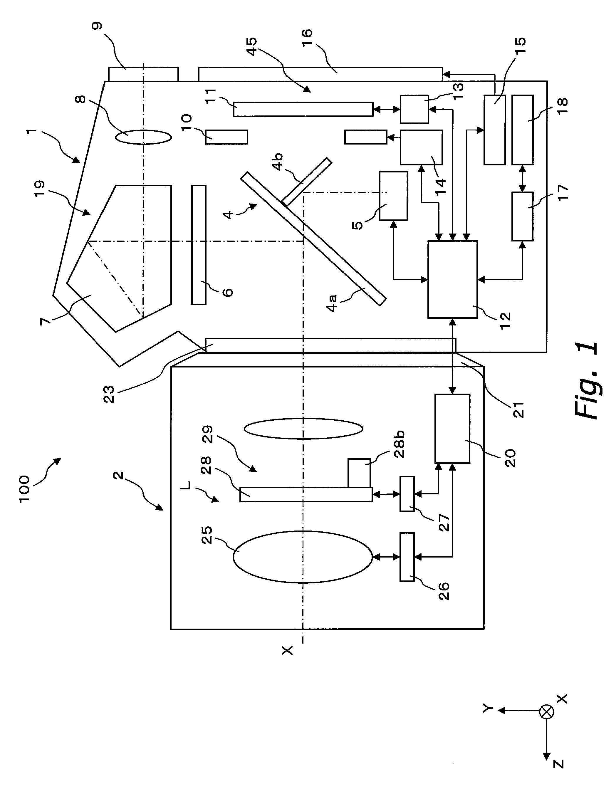
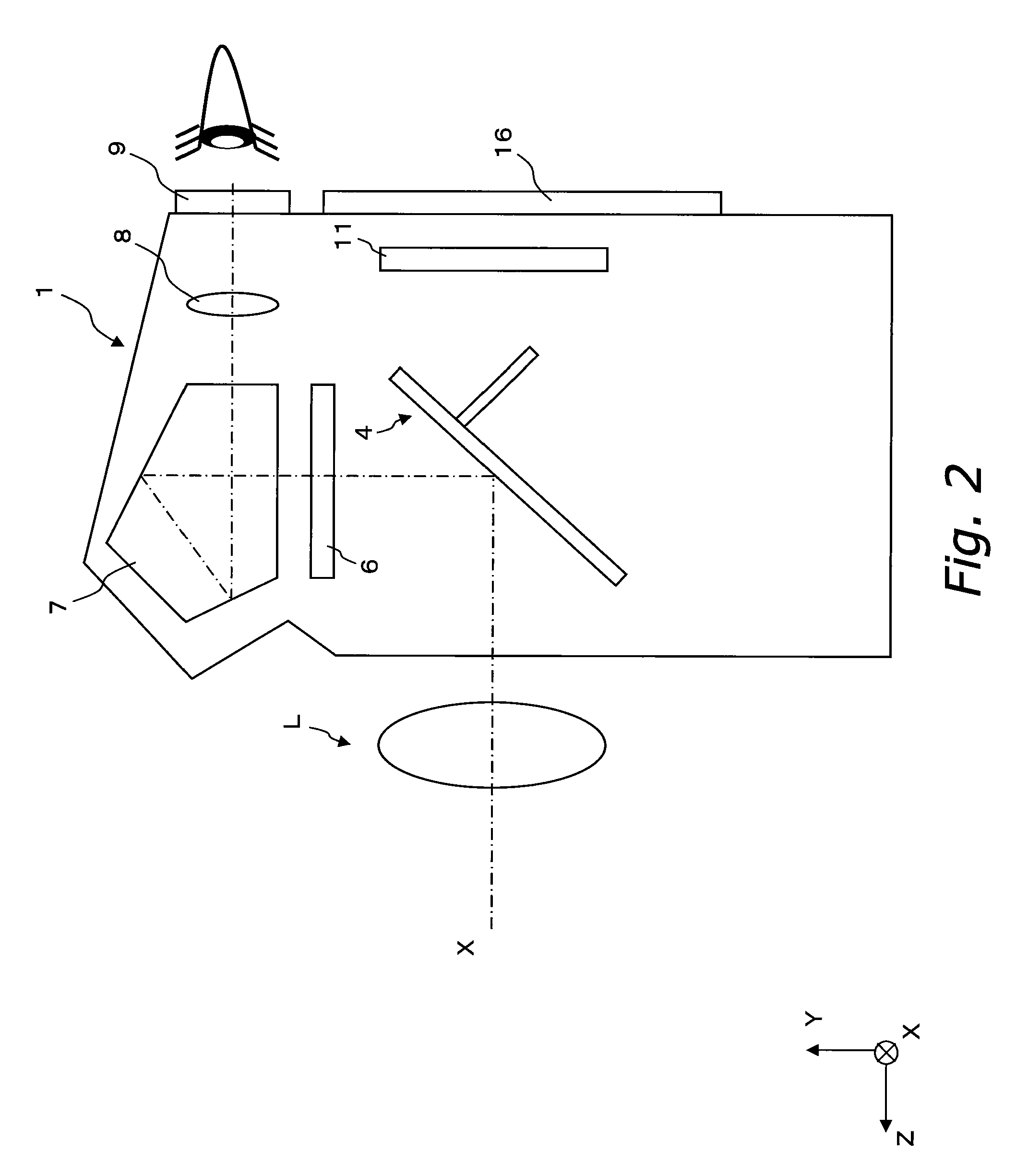
[0048]The camera system 100 pertaining to the first embodiment of the present invention will be described. FIG. 1 is a diagram of the overall configuration of the camera system 100 pertaining to the first embodiment of the present invention.

[0049]The camera system 100 shown in FIG. 1 is an interchangeable lens type of single-lens reflex digital camera system. The camera system 100 includes a camera main body 1 and an interchangeable lens unit 2.

[0050]The camera system 100 and the interchangeable lens unit 2 exchange various control signals via an electrical contact (not shown) of a lens mount 21 on the interchangeable lens unit 2 side and an electrical contact (not shown) of a body mount 23 on the camera system 100 side.

[0051]1.1: Configuration of Interchangeable Lens Unit

[0052]The interchangeable lens unit 2 mainly includes an imaging opt...


PUM


Abstract

A camera system has an imaging optical system, an imaging component, a liquid crystal monitor, an aperture setting component, and an image display controller. The liquid crystal monitor has a first display region and a second display region. The aperture setting component adjusts the aperture in a specific period so that the actual aperture value will be a preset value. The image display controller displays, in the first display region, a reference image acquired by the imaging component under conditions in which the aperture value is the preset value, and displays, in the second display region, a comparative image acquired by the imaging component at a different timing from that of the reference image.

Description

CROSS-REFERENCE TO RELATED APPLICATIONS[0001]This application claims priority to Japanese Patent Application No. JP2007-146503 filed on Jun. 1, 2007. The entire disclosure of Japanese Patent Application No. JP2007-146503 is hereby incorporated herein by reference.BACKGROUND OF THE INVENTION[0002]1. Field of the Invention[0003]The present invention relates to a camera system, and more particularly relates to a camera system with which a plurality of images can be displayed side by side.[0004]2. Background Information[0005]Single-lens reflex digital cameras have become tremendously popular in recent years. With a single-lens reflex digital camera, when an optical viewfinder is used to view a subject, the light incident on the imaging optical system is reflected by a reflecting mirror disposed along the optical path, and is guided to the viewfinder optical system. As a result, the subject image is converted by a pentaprism or the like into an erect image before being guided to the view...

Claims


Application Information

Patent Timeline
Patent Type & Authority Patents(United States)
IPC IPC(8): H04N5/222H04N5/262H04N5/228H04N9/74
CPCG03B13/30G03B17/20G03B19/12H04N5/23293H04N5/772H04N5/907H04N9/8042H04N23/63
Inventor HONJO, KENICHIYUMIKI, NAOTO
Owner PANASONIC CORP
Why Eureka
Try Eureka