[0009]Additional aspects and / or advantages of the invention will be set forth in part in the description which follows and, in part, will be apparent from the description, or may be learned by practice of the invention.
[0010]To achieve at least the above and / or other aspects and advantages, embodiments of the present invention include a system correcting a display image. The system includes a parameter calculation module to calculate a plurality of parameters required for a transform of a first image, based on a plurality of characteristic differences between the first image and a second image, into which the first image is to be transformed to visually match the second image, a first characteristic transform module to transform a first characteristic of the first image using the plurality of calculated parameters, the transformation resulting in an unrelated change to a second characteristic of the first image, and a second characteristic restoration module to restore the second characteristic changed by the transforming of the first characteristic.
[0011]To achieve at least the above and / or other aspects and advantages, embodiments of the present invention include a method correcting a display image. The method includes calculating a plurality of parameters required for a transform of a first image, based on a plurality of characteristic differences between the first image and a second image, into which the first image is to be transformed to visually match the second image, transforming a first characteristic of the first image using the plurality of calculated parameters, the transforming of the first characteristic resulting in an unrelated change to a second characteristic of the first image, and restoring the second characteristic changed by the transforming of the first characteristic.
[0011]To achieve at least the above and / or other aspects and advantages, embodiments of the present invention include a method correcting a display image. The method includes calculating a plurality of parameters required for a transform of a first image, based on a plurality of characteristic differences between the first image and a second image, into which the first image is to be transformed to visually match the second image, transforming a first characteristic of the first image using the plurality of calculated parameters, the transforming of the first characteristic resulting in an unrelated change to a second characteristic of the first image, and restoring the second characteristic changed by the transforming of the first characteristic.
[0013]These and / or other aspects and advantages of the invention will become apparent and more readily appreciated from the following description of embodiments, taken in conjunction with the accompanying drawings of which:
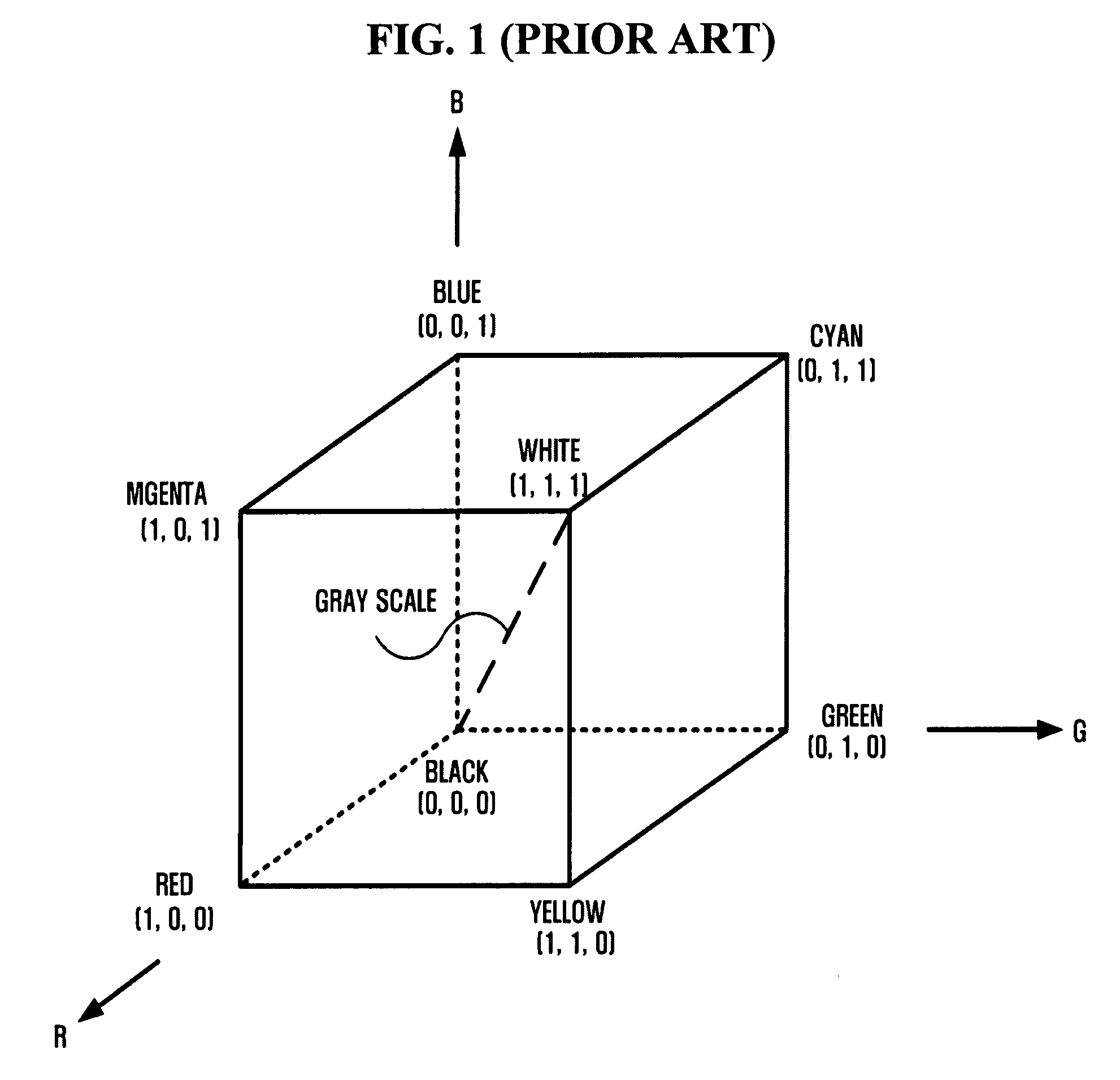
[0014]FIG. 1 illustrates a red, green, and blue (RGB) color model;
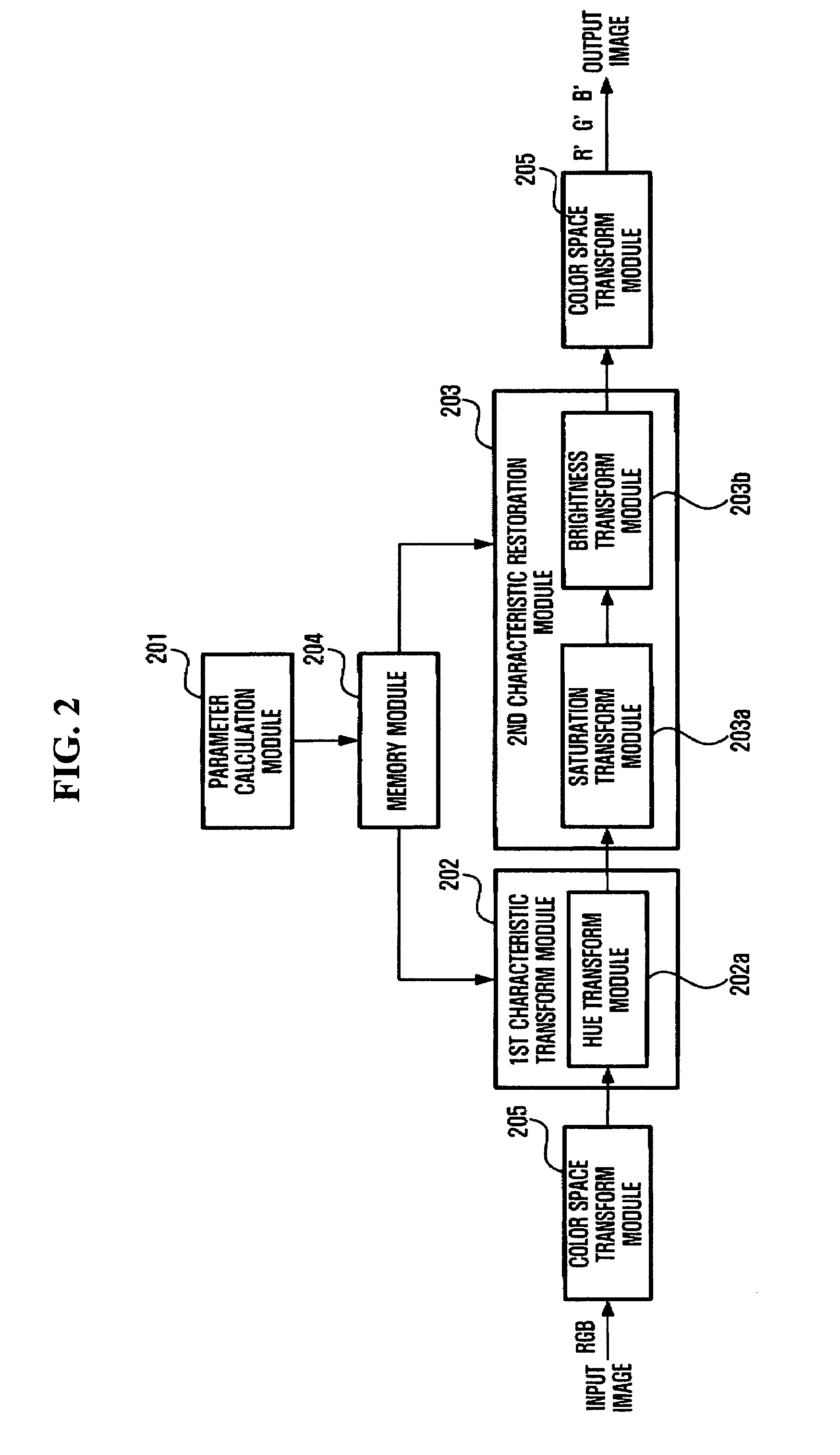
[0015]FIG. 2 is a block diagram illustrating a system correcting the color of a display image according to an embodiment of the present invention;
[0016]FIG. 3 illustrates a flow chart for a color transform parameter calculation module, such as that illustrated in FIG. 2, according to an embodiment of the present invention;
[0017]FIG. 4 illustrates a hue, saturation, and value (HSV) color model;
[0018]FIG. 5 illustrates the result of a color transform performed by a color transform module, such as that illustrated in FIG. 2, according to an embodiment of the present invention;
[0019]FIG. 6 illustrates a result of a saturation transform, such as performed by a saturation transform module illustrated in FIG. 2, according to an embodiment of the present invention;
[0020]FIG. 7 illustrates a result of brightness correction by a brightness correction module illustrated in FIG. 2, according to an embodiment of the present invention; and
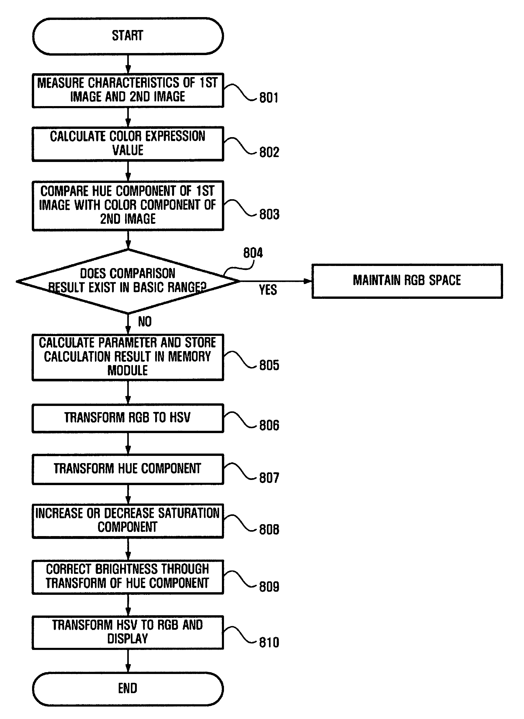
[0021]FIG. 8 illustrates a method of correcting a color of a display image, according to an embodiment of the present invention.
[0022]Reference will now be made in detail to embodiments of the present invention, examples of which are illustrated in the accompanying drawings, wherein like reference numerals refer to like elements throughout. Embodiments are described below to explain the present invention by referring to the figures.
[0023]Representative color models such as CIE, CIELab, RGB (Red, Green and Blue), CYM (Cyan, Magenta and Yellow), CMYK (Cyan, Magenta, Yellow, and black), or HSV (Hue, Saturation, and Value for brightness) value models, may be used to describe colors in a specific environment using an objective color evaluating technique. These models may be used for output apparatuses, such as display apparatuses or printers, or used for intuitive color designation by a person. Accordingly, as references thereto will be made in aspects of the present invention, first such color models will be briefly explained.
[0023]Representative color models such as CIE, CIELab, RGB (Red, Green and Blue), CYM (Cyan, Magenta and Yellow), CMYK (Cyan, Magenta, Yellow, and black), or HSV (Hue, Saturation, and Value for brightness) value models, may be used to describe colors in a specific environment using an objective color evaluating technique. These models may be used for output apparatuses, such as display apparatuses or printers, or used for intuitive color designation by a person. Accordingly, as references thereto will be made in aspects of the present invention, first such color models will be briefly explained.
[0025]The CIE color model was first developed by the International Commission on Illumination (Commission Internationale de l'Eclairage) in 1931 to specify colors in the visible spectrum using three primary colors.
[0026]Since all colors cannot be displayed with three primary colors in a visible region, virtual colors that do not exist are defined with reference to the primary colors in the CIE model.
[0027]The CIE color model provides a standard for colors and is convenient for comparing color regions between two difference devices or applications.
[0028]For example, if three ink colors of a printer and the color region of the RGB color of a monitor are displayed in the CIE model, it may be determined which colors cannot be output.
[0029]Meanwhile, the CIELab color model is designed to reproduce identical colors in different types of monitors or printers or both. The CIELab color model was developed in 1976 based on the CIE model.
[0030]The CIELab color model is defined by brightness (Lightness) and two color regions (a and b). The “a” color region is distributed from green to red, and the “b” color region is distributed from blue to yellow.
[0031]Here, the region of colors that can be represented by a predetermined color model (RGB, CMYK, etc.) is referred to as a gamut. Since the CIELab color model has a gamut that includes both the CMYK and RGB models, it is used in an intermediate state when a color model is changed in the popular software Photoshop™, for example.
[0033]The RGB color model is a model based on a tri-stimulus principle of color vision, in which a color is sensed with respect to the degree of excitement of three visual pigments at the retina of our eyes (visual pigments, red, green and blue, in the retina of our eyes have a maximum brightness at a 630 mm wavelength, a 530 mm wavelength, and a 450 mm wavelength, respectively).
[0034]In the RGB color model, other colors are represented using references to the three color values, red, green, and blue.
[0035]For example, if R=1, G=1, and B=0, that is, (1,1,0), the color becomes yellow.
[0036]In the RGB color model, the range of each value, R, G, and B, can be indicated using decimal fractions between 0 and 1, but in most of graphic software programs, values from 0 to 255 are used.
[0037]Further, in the RGB color model, the entire range of colors can be represented as a cube, and this is illustrated in FIG. 1. The cube provides a three-dimensional space wherein each possible color occupies a unique position within the cube. Referring to the cube in FIG. 1, the origin (0,0,0) represents the color black, coordinates (1,1,1) represent the color white, and the other corners represent the basic RGB colors and combined colors.
[0038]For example, gray scale appears on the line connecting (0,0,0) and (1,1,1). That is, if the three values of R, G, and B are the same, the resulting value becomes a gray scale color.
[0039]Many displays, including TVs and computer monitors such as cathode-ray tubes (CRT) and liquid crystal displays (LCD), operate based on the RGB color model.
[0040]Inside the monitor screen of the displays, there are electron guns of three colors. Electron beams emitted from these electron guns collide with the fluorescent surface of the insides of color cells of the screen, thereby generating light.
[0041]If the three electron guns emit electron beams to a color cell at the same time at maximum intensities, the color will be seen as white. Conversely, if no electron guns emit electron beams, the corresponding point will be seen as black.
[0042]In this example, each electron gun emits electron beams in 256-stepped intensities, and the color of one point is generated when the three electron guns emit R, G, and B colors, respectively, to a color cell. Accordingly, 256×256×256 (i.e., over 16 million) different colors can be theoretically displayed on the screen.
[0043]This number is far beyond the 400,000 different colors that can be recognized by the unaided human eye, and is generally more than sufficient to represent the world visible to human eyes.
[0044]In order to store the color value of one point, a total of 24 bits, including 8 bits for each of R, G, and B are typically required, and this is referred to as “24-bit true color”.
[0045]Adjusting the contrast of an image is one way to correct color in a display apparatus using the RGB color model.
[0046]Here, contrast refers to a difference between gray level values or luminance values in a predetermined area of an image. To adjust the contrast, the contrast is changed using a linear transform such as g(x,y)=T[f(x,y)], or a nonlinear transform T (for example, a log transform), or a histogram equalization method, in which a histogram h(g) of an image is extracted and histograms of higher values and lower values are weakened, thereby providing an image which is smoothed overall.
[0047]However, the method of increasing the contrast of an image in the RGB color model may cause distortion of color throughout the entire image.
[0049]The CMY color model has cyan, magenta, and yellow as primary colors, and has a shape obtained by making RGB color models face each other on diagonal lines.
[0050]The above RGB color model is based on an additive process, in which the result is white (1,1,1) if three colors, R, G, and B, are added. In contrast, the CMY color model is based on a subtractive process in which the result is black (1,1,1) if three colors, C, M, and Y, are added.
[0051]In actuality, if inks of C, M, Y colors are mixed, the result becomes dark gray. If a black ink is used in addition to the C, M and Y, color inks can be saved when a dark color is displayed. Accordingly, for printer output, a CMYK color model is used in which black K is added to the CMY color model. It is typically desirable to use black ink rather than color inks because black ink is much cheaper than color inks. For reference, the CMY color model is mainly used for output colors of a device, such as a printer, in which ink is used to produce a hard copy.
[0053]The RGB color model and the CMY color model are designed for displays and printing devices, respectively, while the HSV color model is designed to provide a more intuitive color specifying method for a user.
[0054]The HSV color model can represent color (hue), saturation, and brightness (value) that cannot be represented in the RGB color model, and is widely used for color correction for displaying natural colors on a display image.
[0055]FIG. 2 illustrates a system correcting the hue of a display image according to an embodiment of the present invention.
[0056]The system 200 may include, for example, a parameter calculation module 201, a first characteristic transform module 202, a second characteristic restoration module 203, a memory module 204 and a color space transform module 205. The parameter calculation module 201 may calculate a plurality of parameters required for a transform or a correction based on a plurality of characteristic differences between a first image currently displayed and a second image, which is a target image of the first image, and may store the calculation result, e.g., in the memory module 204. The first characteristic transform module 202 may transform a first characteristic of the first image by using the plurality of calculated parameters. The second characteristic restoration module 203 may restore a second characteristic changed due to the transforming of the first characteristic. The memory module 205 may store parameters required for a transform, and the color space transform module 205 may transform a color space, noting that alternative embodiments are equally available.
[0057]In addition, the first characteristic transform module 202 may include, for example, a hue transform module 202A to perform a hue transform, while the second characteristic restoration module 203 may include, for example, a saturation transform module 203A and a brightness transform module 203B to perform transformation of saturation and brightness, respectively.
[0058]The hue transform module 202A may transform the hue component of the first image, using the parameters calculated in the parameter calculation module 201, and the saturation transform module 203A may increase or decrease the saturation component in a predetermined hue region in the first image, using the transform degree of the hue component and the calculated parameters.
[0059]The brightness transform module 203B may correct a change in brightness caused by the hue component change, using the maximum brightness information for each color, for example.