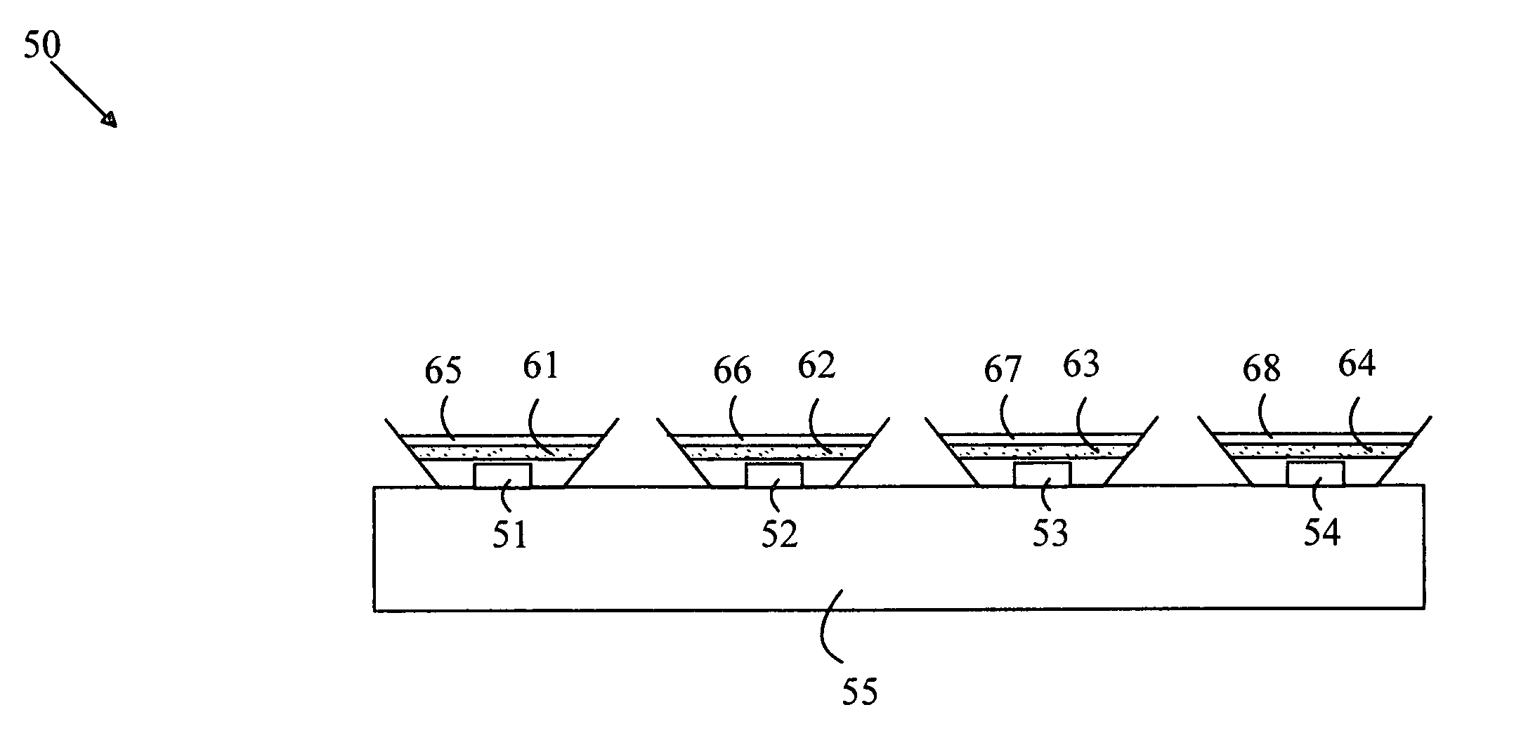
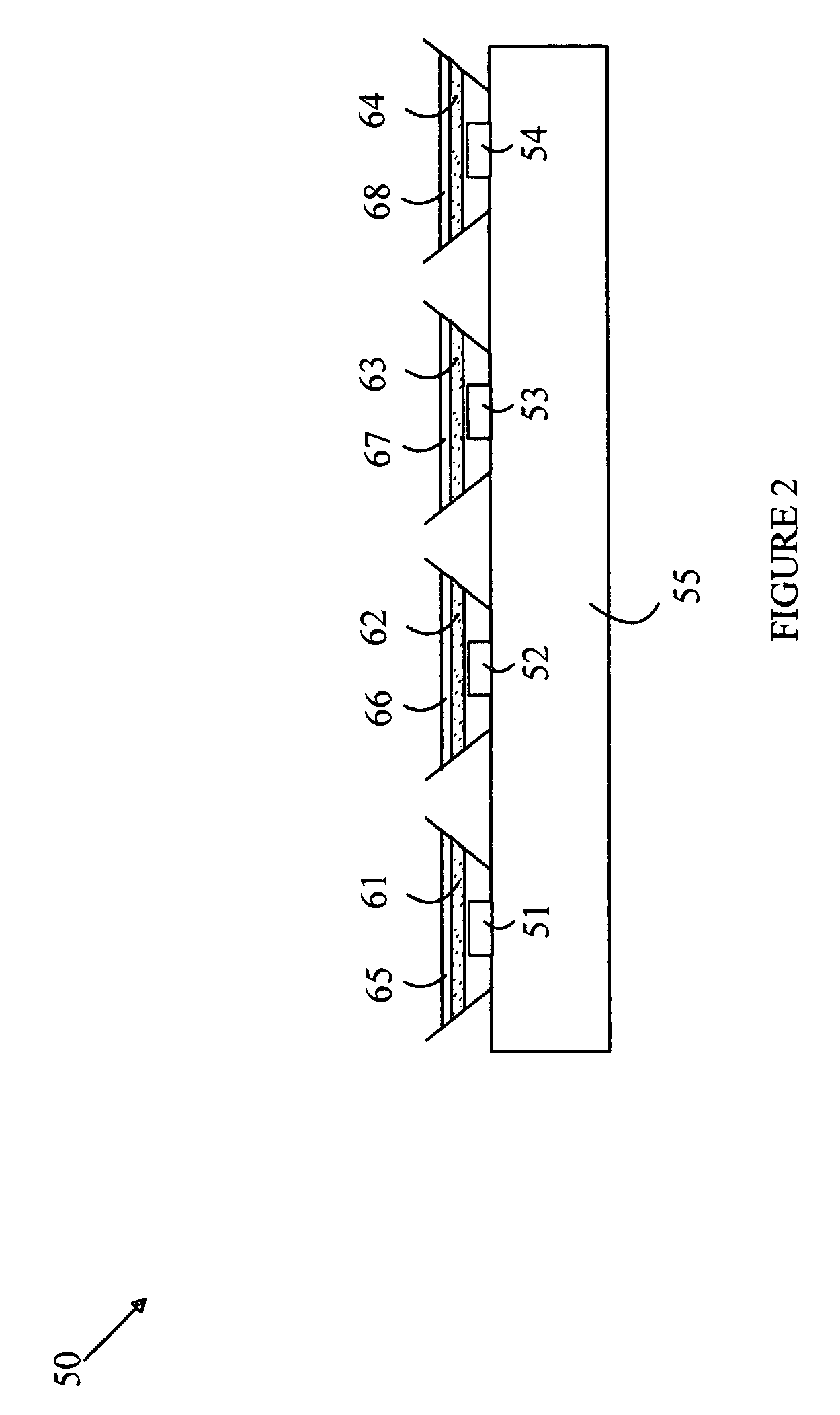
Phosphor converted light source

a light source and phosphor technology, applied in the field of phosphor converted light sources, can solve the problems of increasing the cost of the light source, light in a relatively narrow spectral band, and the output of individual leds

Active Publication Date: 2006-11-23
INTELLECTUAL DISCOVERY CO LTD
View PDF14 Cites 44 Cited by
  • Summary
  • Abstract
  • Description
  • Claims
  • Application Information

AI Technical Summary

Problems solved by technology

Unfortunately, LEDs produce light in a relatively narrow spectral band.
Unfortunately, the output of the individual LEDs varies with temperature, drive current, and aging.
Such feedback systems increase the cost of the light source.
Unfortunately, many li

Method used


Image

  • Phosphor converted light source
  • Phosphor converted light source
  • Phosphor converted light source

Examples


Embodiment Construction

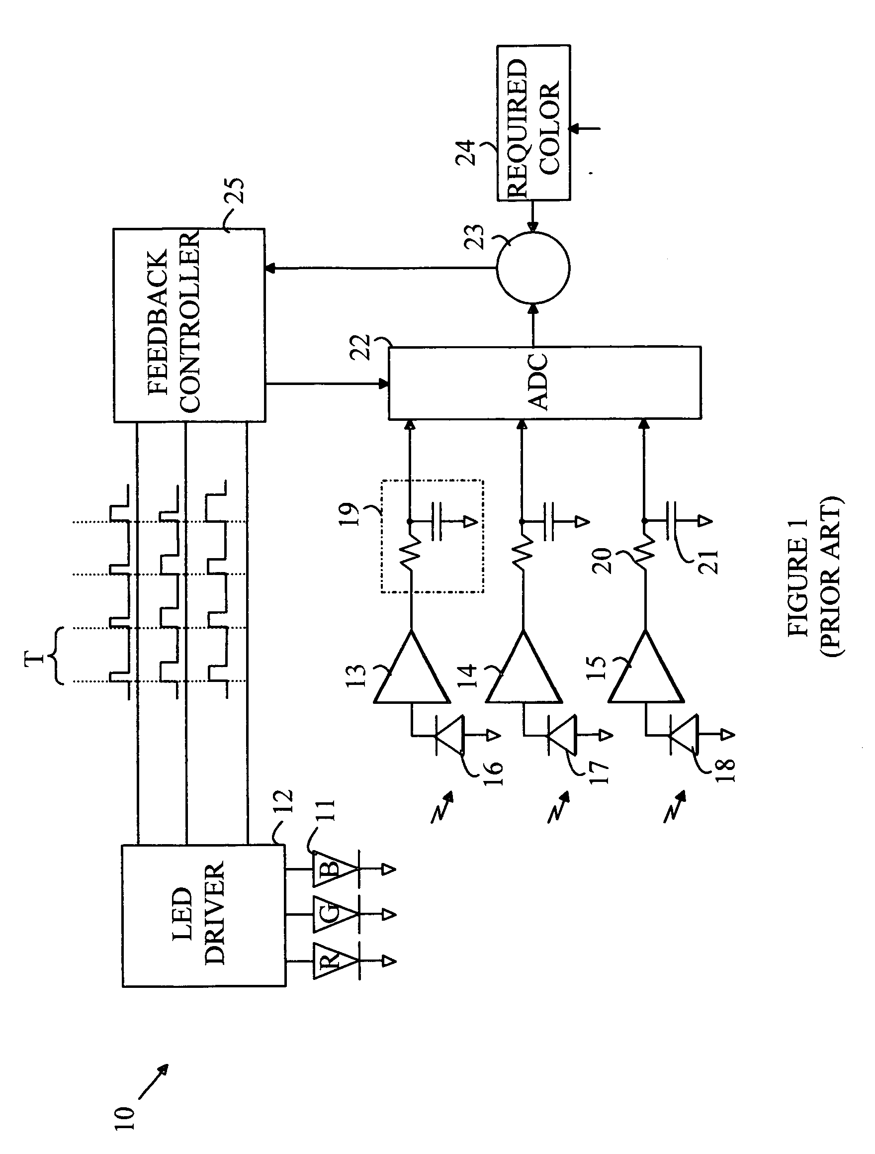
[0009] The manner in which the present invention provides its advantages can be more easily understood with reference to FIG. 1. FIG. 1 is a block diagram of a prior art LED light source that utilizes a feedback system to control the duty factor of the individual LEDs to produce a precise output color. Light source 10 utilizes red, green, and blue LEDs 11 to generate light of an arbitrary color. The LEDs are driven by a driver 12 that sets the current through each LED when that LED is “on”. In the “on” state, each LED is driven with a predetermined current that is independent of the color being generated by light source 10. The LEDs are driven in a pulsed manner with a cycle time having a period T. During each period, each of the LEDs is turned on for a time t that depends on the color of light that is to be generated by light source 10.

[0010] To simplify the following discussion the ratio t / T will be referred to as the duty factor. In principle, the intensity of the light, as seen...


PUM


Abstract

A light source having first and second phosphor-converted component light sources is disclosed. The first component light source includes a first LED that emits light at a first wavelength and a first luminescent conversion material layer that converts light of the first wavelength to light of a first output wavelength, and the second component light source includes a second LED that emits light at a second wavelength and a second luminescent conversion material layer that converts light of the second wavelength to light of a second output wavelength that is different from the first output wavelength. The first and second LEDs are constructed in the same material system, preferably in the same batch of wafers on the fabrication line. A controller generates a current through each of the first and second LEDs that results in the light source generating light that is perceived to be a predetermined color.

Description

BACKGROUND OF THE INVENTION [0001] Light emitting diodes (LEDs) are attractive candidates for replacing conventional light sources such as incandescent lamps and fluorescent light sources. The LEDs have higher electrical-to-light conversion efficiencies and longer lifetimes than incandescent lamps, and do not require the high operating voltages associated with fluorescent light sources. In addition, it is expected that the light conversion efficiencies of LEDs will continue to increase to the point where LEDs will also provide higher conversion efficiencies than fluorescent light sources. [0002] Unfortunately, LEDs produce light in a relatively narrow spectral band. Hence, to produce a light source having an arbitrary color, a compound light source having multiple LEDs is typically utilized. For example, an LED-based light source that provides an emission that is perceived as matching a particular color can be constructed by combining light from red, green, and blue emitting LEDs. T...

Claims


Application Information

Patent Timeline
IPC IPC(8): H05B37/00F21K99/00H01L33/48H01L33/50H01L33/54H01L33/56
CPCH05B33/0818H05B33/0821Y10S362/80H05B33/0869H05B33/0863H05B45/20H05B45/22H05B45/397Y02B20/30
Inventor NG, KEE YEANCHENG, HENG YOWCHUA, JANET BEE YIN
Owner INTELLECTUAL DISCOVERY CO LTD
Why Eureka
Try Eureka