Image processing apparatus and method, and computer program

Inactive Publication Date: 2005-08-04
SONY CORP
View PDF6 Cites 44 Cited by
  • Summary
  • Abstract
  • Description
  • Claims
  • Application Information

AI Technical Summary

Benefits of technology

[0019] Accordingly, it is an object of the present invention to provide an image processing apparatus and method for performing accurate color correction for photographed im

Problems solved by technology

In this method, a moving object can be photographed, which is not possible by using a single camera; however, a problem of color variations due to the difference among the cameras still exists.
Thus, a high-quality mosaic image, such as a panoramic picture, cannot be obtained.
In particular, a composite picture m

Method used


Image

  • Image processing apparatus and method, and computer program
  • Image processing apparatus and method, and computer program
  • Image processing apparatus and method, and computer program

Examples


first embodiment

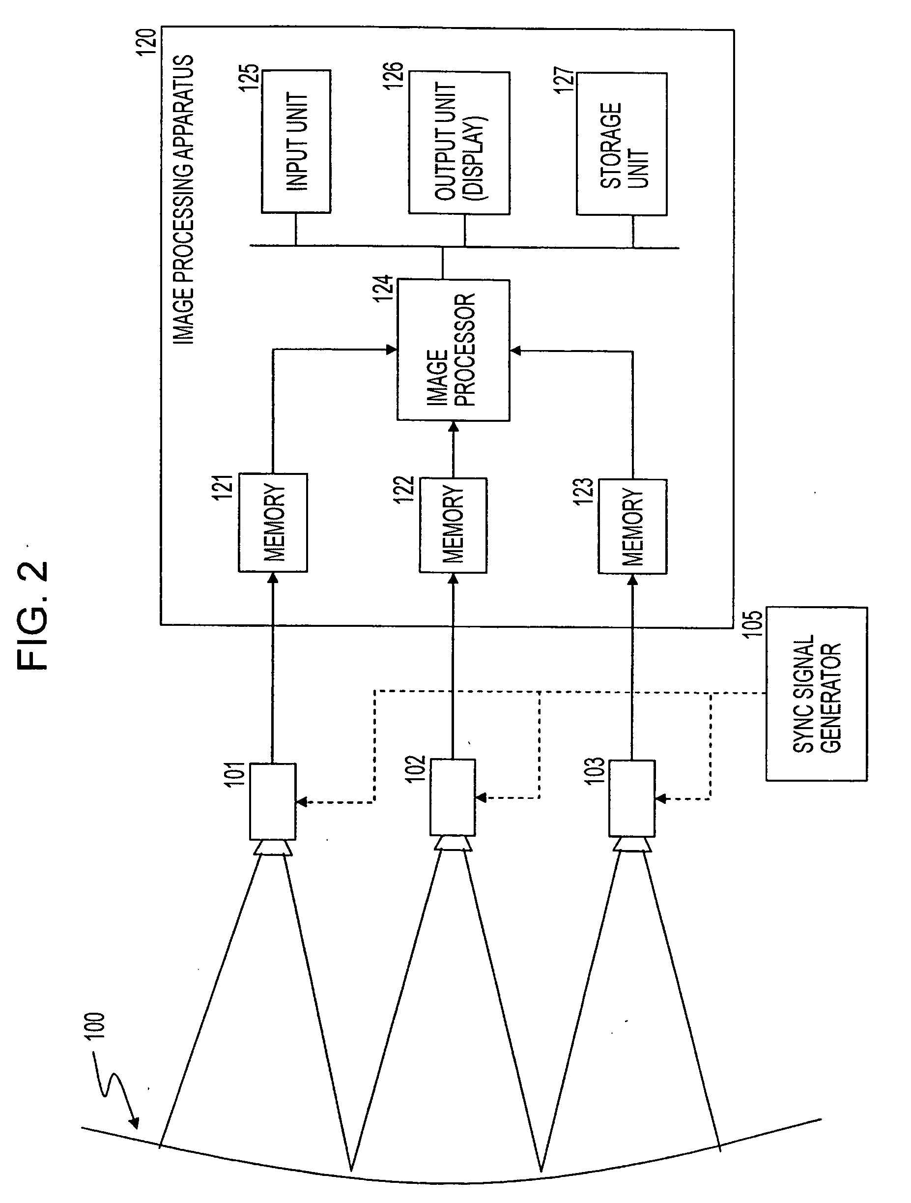
[0062]FIG. 2 is a block diagram of an image processing apparatus according to the present invention for capturing photographed images.

[0063] An object 100 is photographed using a plurality of cameras 101 to 103. The cameras 101 to 103 photograph the object in different object scene regions. For example, the cameras 101 to 103 receive a sync signal output from a sync signal generator 105, and the photographing timing of the cameras 101 to 103 is controlled. Although three cameras are shown in FIG. 2, the present invention is applicable to processing of images photographed from a plurality of different viewpoints, and any number of cameras may be used. The present invention is also applicable to processing of a plurality of images photographed using a single camera while sequentially changing the viewpoint. In the first embodiment, images photographed using a plurality of different cameras are processed, by way of example.

[0064] An image processing apparatus 120 receives image data ...

second embodiment

[0144] An image processing apparatus according to a second embodiment of the present invention will be described. In the first embodiment, the output pixel values of the pixels constituting the correction image (designated camera image) 201 are uniformly corrected using a transformed tone curve.

[0145] In the second embodiment, the output pixel values of the pixels constituting the correction image (designated camera image) 201 are corrected using a transformed tone curve while changing the amount of correction depending upon the distance from the reference image 202.

[0146] The image processing apparatus of the second embodiment has a similar structure to that of the first embodiment described above with reference to FIG. 2.

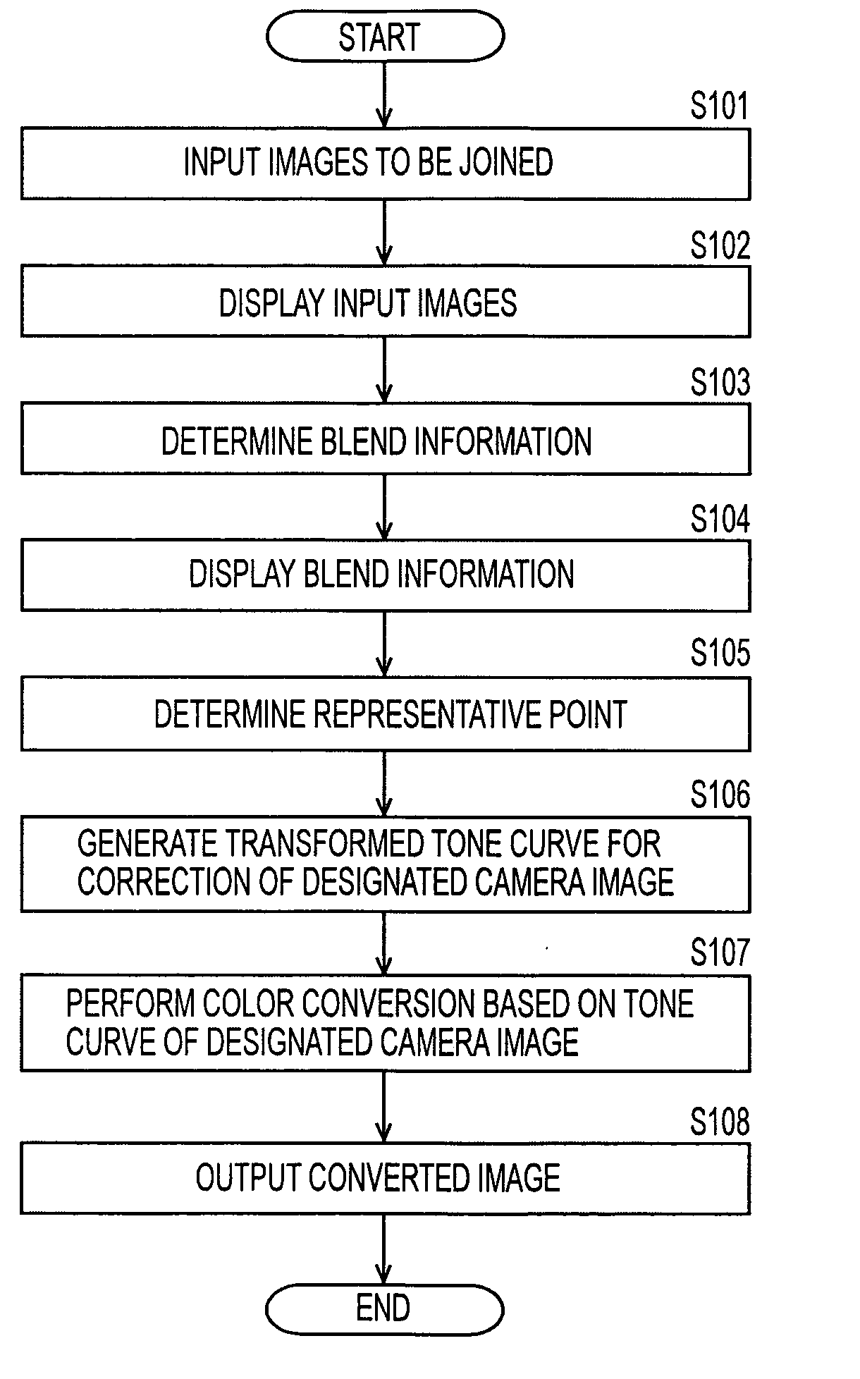
[0147] An image processing procedure according to the second embodiment will be described with reference to FIG. 13. In the procedure shown in FIG. 13, the tone curve transformation processing of steps S201 to S206 is similar to the processing of steps S101 to ...

third embodiment

[0158] In the first and second embodiments, as described above with reference to FIG. 7, a representative point is selected by the operator. The composite image constituted by the correction image (designated camera image) 201 and the reference image 202 is shown on the display, and a point at which the same color should be set is selected from each of the correction image (designated camera image) 201 and the reference image 202 of the composite image data.

[0159] In the example shown in FIG. 7, a representative point at which the same color should be set is included in a “sky” region of the photographed scene. In FIG. 7, the representative point 301 (X1, Y1) is selected in the correction image (designated camera image) 201, and the representative point 302 (X2, Y2) is selected in the reference image 202.

[0160] In a third embodiment of the present invention, representative point selection is automatically performed. In a representative point selection process, an edge image corres...


PUM


Abstract

A representative point for pixel value adjustment at which the same pixel value is to be set is selected from each of a correction image to be corrected and a reference image of a mosaic image. A tone curve that defines an output pixel value with respect to an input pixel value is generated by a line that passes through a pixel-value-conversion coordinate point defined by pixel values indicating the representative points selected from the correction image and the reference image, which are set as input and output values. This line is generated by a spline curve. The pixel value of the correction image is converted based on the generated tone curve.

Description

BACKGROUND OF THE INVENTION [0001] 1. Field of the Invention [0002] The present invention relates to an image processing apparatus and method and a computer program. More specifically, the present invention relates to an image processing apparatus and method for correcting for color variations in a mosaic image (multi-view image) produced by joining a plurality of images photographed from different viewpoints, and to a computer program. [0003] 2. Description of the Related Art [0004] Panoramic pictures or star maps are produced by joining camera pictures photographed from different viewpoints. An object may be photographed from different viewpoints using a single camera or a plurality of cameras. [0005] An object may be photographed using a single camera that is manually or automatically pointed in many directions to obtain multi-view images of the object, and the images may then be joined. In this case, the object is not photographed from a plurality of viewpoints at the same time....

Claims


Application Information

Patent Timeline
IPC IPC(8): G06K9/00G06K9/36G06T3/00G06T5/00G06T7/60H04N1/387H04N1/407H04N5/265
CPCH04N1/407H04N1/3876
Inventor HASEGAWA, YUICHI
Owner SONY CORP
Why Eureka
Try Eureka