

C-band disinfector
a disinfector and band technology, applied in the field of cband disinfectors, can solve the problems of difficult to reach and disinfect interior channels or conduits, ineffective disinfection methods, and spread of contaminants
- Summary
- Abstract
- Description
- Claims
- Application Information
AI Technical Summary
Benefits of technology
Problems solved by technology
Method used
Image

Examples
Embodiment Construction
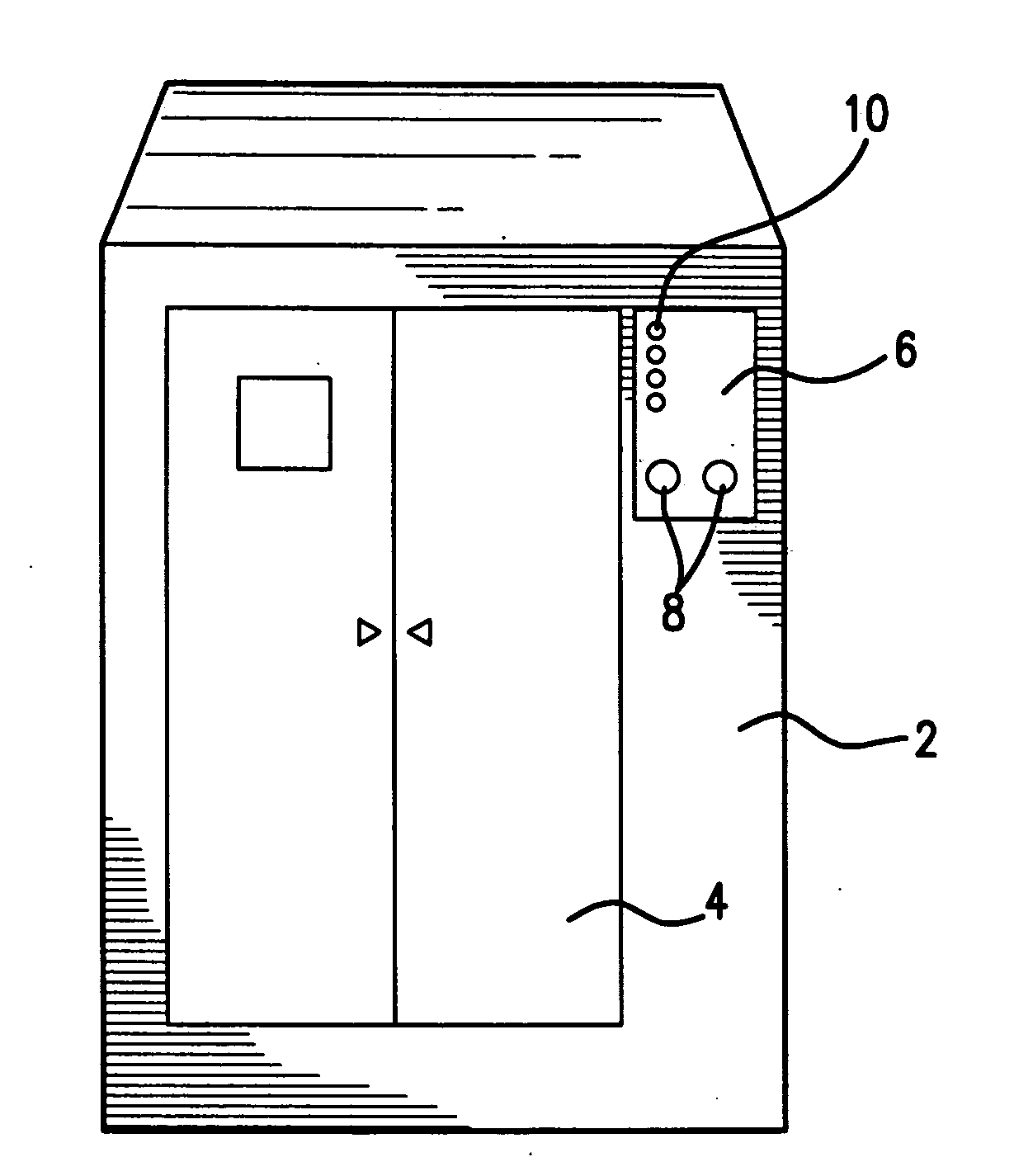
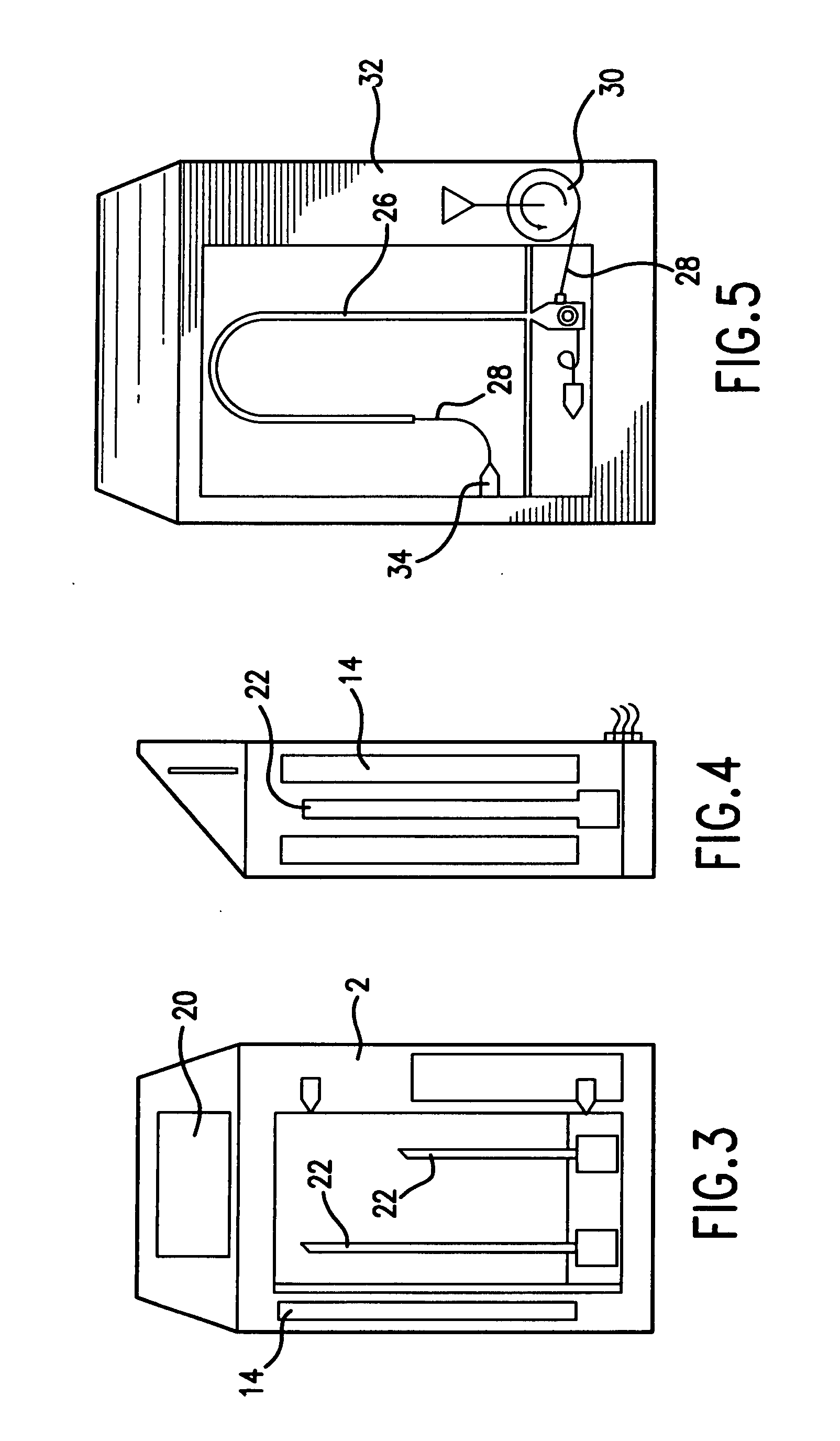
[0018] The C-Band Disinfector provides decontamination of medical instruments and other objects, with little or no risk of harm to the instruments or objects during the process. The device uses medium pressure mercury bulbs, or other bulbs that produce ultraviolet light in the UV-C range, housed in a vertical chamber to irradiate the exterior of an object, such as medical instrument.
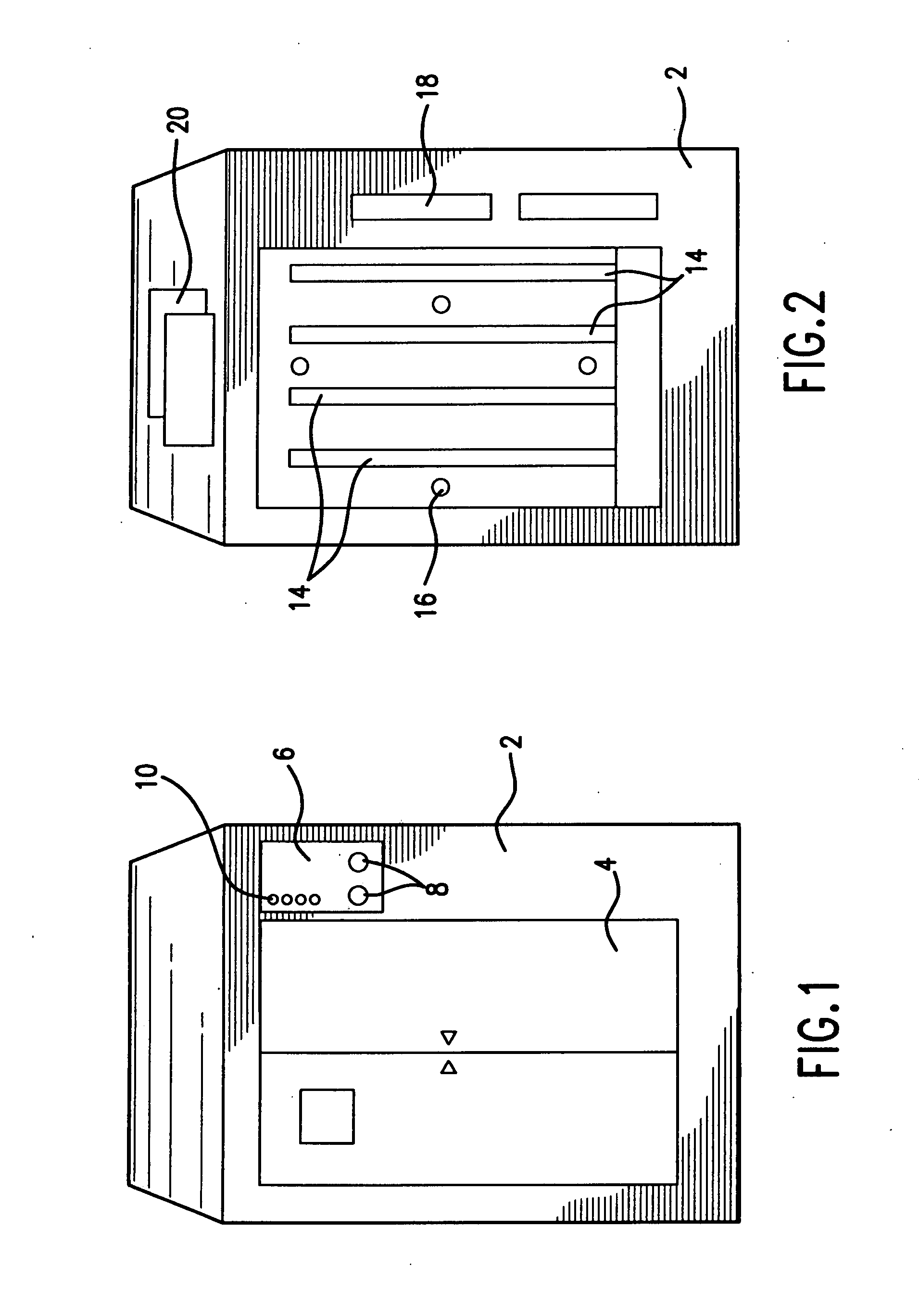
[0019]FIG. 1 shows a housing for an embodiment of the device. The housing 2 is preferred to be formed of a metal that is easy to clean, such as stainless steel or powder coated steel. All interior surfaces are preferred to be highly UV-C reflective and configured so as to maximize the dispersion of the reflected UV-C radiation within the sterilization chamber. The reflectivity of the interior surfaces of the housing should not be less than 80%. The device may be capable of floor or wall mounting, according to the user's preference, and according to the overall size of the device.
[0020] The interior is ...
PUM
| Property | Measurement | Unit |
|---|---|---|
| reflectivity | aaaaa | aaaaa |
| wavelengths | aaaaa | aaaaa |
| velocity | aaaaa | aaaaa |
Abstract
Description
Claims
Application Information