Optical amplification method and device usable with bands other than the C-band

a technology of optical amplification and band, applied in the direction of semiconductor amplifier structure, multiplex communication, electronic repeaters, etc., can solve the problems of limited 1610 to 1650 nm band, small gain per unit length, and difficulty in success of optical amplification, so as to achieve the effect of attenuating the wavelength gain peak

Inactive Publication Date: 2009-01-20
FUJITSU LTD
View PDF58 Cites 4 Cited by
  • Summary
  • Abstract
  • Description
  • Claims
  • Application Information

AI Technical Summary

Problems solved by technology

In FIG. 1, even though GS-TDFA (gain-shifted thulium-doped fluoride-based fiber amplifiers) are being developed for amplification in the S band region from 1490 nm to 1530 nm, GS-TDFA devices have a gain in the region between 1475 and 1510 nm, and thus it may be difficult for them to succeed in the portion of S band extending from 1510 to 1530 nm.
In addition, the 1610 to 1650 nm band is limited to specialty fibers that are either thulium or terbium-doped fluoride-based fibers.
However, there are problems in that the gain per unit length is small, so the optical amplification fibers must placed every several kilometers to every several dozen kilometers within the transmission line.

Method used


Image

  • Optical amplification method and device usable with bands other than the C-band
  • Optical amplification method and device usable with bands other than the C-band
  • Optical amplification method and device usable with bands other than the C-band

Examples


Embodiment Construction

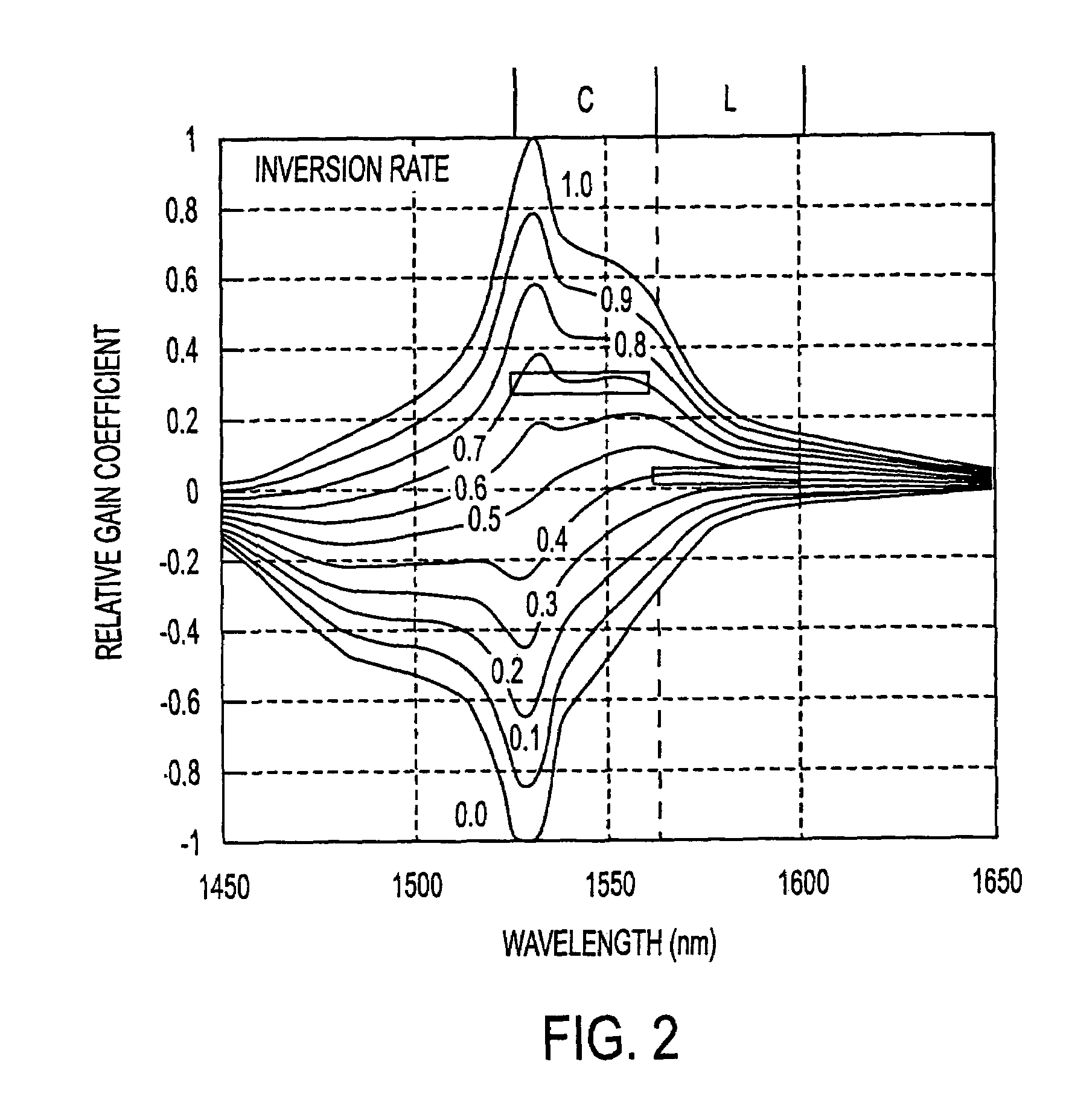
[0041]FIG. 2 shows the wavelength gain characteristics in terms of relative gain coefficients, or gain coefficient (dB / m), for silica erbium-doped fiber (EDF) amplifiers. The population inversion rates are defined by the proportion of the erbium ions that are excited. The rate is 1.0 when all of the ions are excited (i.e., when all electrons are excited to a higher level), and if none of the ions are excited (i.e., all are in the non-excited level), then the population inversion rate is 0.0. The relative gain coefficient is labeled on the vertical axis as the gain per unit length.

[0042]FIG. 2 corresponds with FIG. 3 of Y. Sun, J. L. Zyskind and A. K. Srivastava, “Average Inversion Level, Modeling, and Physics of Erbium-Doped Fiber Amplifiers,” IEEE Journal of Selected Topics in Quantum Electronics, Vol. 3, No. 4, pp. 991-1007, August 1997. The relative gain coefficients shown in FIG. 2 are applicable to any of a plurality of amplification mediums. The FIG. 2 relative gain coefficien...


PUM


Abstract

An optical amplifier includes an optical amplification medium, an excitation source to stimulate the amplification medium to output at least one wavelength gain peak, and a gain equalizer to equalize the output of the amplification medium such that gain is produced at wavelengths other than the wavelength gain peak. The gain equalizer may attenuate gain at the peak wavelength. The gain equalizer may equalize the output of the amplification medium such that gain is produced at wavelengths less than the wavelength gain peak. The optical amplifier may include both a gain equalizer and automatic level control circuitry to respectively maintain substantially uniform gain at wavelengths within an optical signal band and maintain constant output power.

Description

[0001]This application is a continuation of application Ser. No. 09 / 790,507, filed Feb. 23, 2001 now U.S. Pat. No. 6,633,429.CROSS REFERENCE TO RELATED APPLICATIONS[0002]This application is based on and hereby claims priority to Japanese Application No. 046467 filed on Feb. 23, 2000 in Japan, the contents of which are hereby incorporated by reference.BACKGROUND OF THE INVENTION[0003]Wavelength division multiplexed (WDM) amplifiers amplify optical signals that are composites of multiple wavelength optical signals. WDM optical communications systems relay multi-wavelength composite optical signals through multiple optical amplifiers.[0004]The band over which losses are low in optical fiber transmission circuits (less than approximately 0.3 dB / km) is the band from 1450 nm to 1650 nm. As shown in FIG. 1, a variety of optical fiber amplification devices have been developed for this transmission band.[0005]At present, with the popularity of cellular telephones and the rapid increase in in...

Claims


Application Information

Patent Timeline
Patent Type & Authority Patents(United States)
IPC IPC(8): H04B10/17H01S3/067H01S3/10H01S3/13H01S5/50H04B10/29H04B10/291H04J14/00H04J14/02
CPCH01S3/06754H01S3/10023H01S3/1301H01S2301/04H01S3/0078H01S3/06758H01S3/10015H01S3/13013
Inventor KINOSHITA, SUSUMUINAGAKI, SHINYA
Owner FUJITSU LTD
Why Eureka
Try Eureka