System and method for adaptive current limit of a switching regulator

a switching regulator and current limit technology, applied in the direction of electric variable regulation, process and machine control, instruments, etc., can solve the problems of increasing input voltage, prone to collapse of stored energy in the inductor,

Active Publication Date: 2015-08-04
SILICON LAB INC
View PDF8 Cites 367 Cited by
  • Summary
  • Abstract
  • Description
  • Claims
  • Application Information

AI Technical Summary

Problems solved by technology

When the current reaches a peak level, the switch is turned off and the stored energy in the inductor tends to collapse and the voltage polarity changes such that it adds to the input voltage.

Method used


Image

  • System and method for adaptive current limit of a switching regulator
  • System and method for adaptive current limit of a switching regulator
  • System and method for adaptive current limit of a switching regulator

Examples


Embodiment Construction

[0018]The following description is presented to enable one of ordinary skill in the art to make and use the present invention as provided within the context of a particular application and its requirements. Various modifications to the preferred embodiment will, however, be apparent to one skilled in the art, and the general principles defined herein may be applied to other embodiments. Therefore, the present invention is not intended to be limited to the particular embodiments shown and described herein, but is to be accorded the widest scope consistent with the principles and novel features herein disclosed.

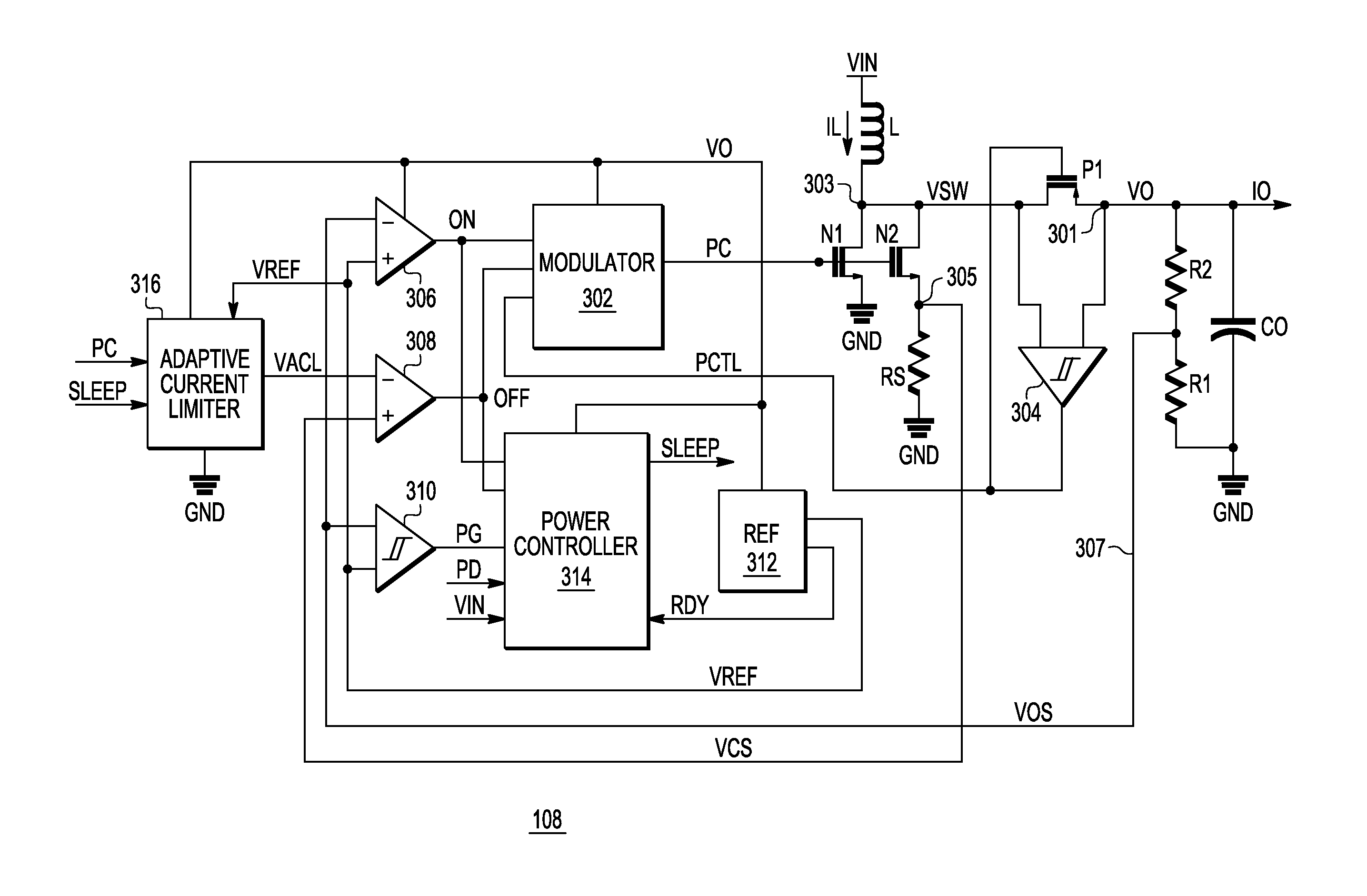
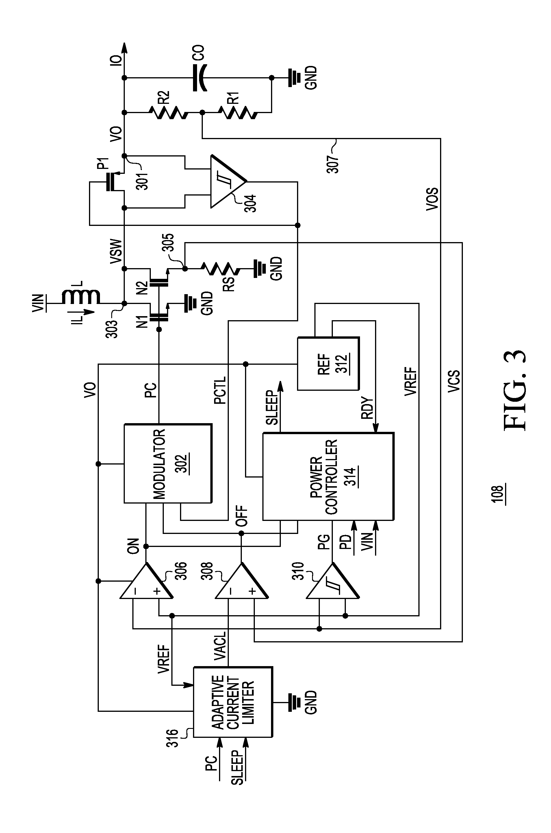
[0019]A switching regulator as described herein develops a pulse control signal to control a switch network (one or more switches) to control current through an inductor to convert an input voltage to an output voltage. In one embodiment, the inductor charges during a first cycle portion and discharges during a second cycle portion to charge an output capacitor. In one embodime...


PUM


Abstract

An adaptive current limiter including a conversion network and an amplifier network developing an adaptive current limit signal for use by a switching regulator to limit peak current through an inductor of the switching regulator. The switching regulator develops a pulse control signal for controlling switching of current through the inductor to convert an input voltage to an output voltage. The conversion network provides a limit value by applying a duty cycle of the pulse control signal to a reference value. The amplifier network is configured to develop the adaptive current limit signal based on the limit value. The conversion network may multiply the reference value by the duty cycle to develop the limit value. The amplifier network may include a current source providing a fixed reference current to an amplifier to establish a minimum level of the adaptive current limit signal.

Description

BACKGROUND OF THE INVENTION[0001]1. Field of the Invention[0002]The present invention relates in general to DC-DC switching regulators, and more particularly to a system and method for adaptive current limit setting of a switching regulator to improve efficiency at lower load levels.[0003]2. Description of the Related Art[0004]A DC (direct current) to DC switching regulator converts an unregulated input DC voltage to a regulated output voltage or otherwise converts voltage from one voltage level to another. A switching regulator typically includes an inductor, a capacitor, a switch network (including at least one switch), a rectifier or rectifying element, a feedback network and a modulator. The modulator monitors one or more sense signals via the feedback network and adjusts a pulse control signal used to control the switch network. The switch network switches voltage applied across the inductor which is used as a storage device to transfer energy from the input voltage to an outpu...

Claims


Application Information

Patent Timeline
Patent Type & Authority Patents(United States)
IPC IPC(8): G05F1/563H02M3/158H02M1/00
CPCH02M3/158H02M2001/0025H02M2001/0032Y02B70/16H02M1/0025H02M1/0032Y02B70/10
Inventor TOOSKY, ZABIHTOMASZ, MARTIN
Owner SILICON LAB INC
Why Eureka
Try Eureka