C-band low-insertion-loss and high-rejection miniature band-pass filter

A high-rejection, C-band technology, applied in the field of filters, can solve the problems of large size and insertion loss, limitations, etc., and achieve the effects of reduced component size, high yield, and low cost

Inactive Publication Date: 2012-09-19
CHANGSHU RES INSTITUE OF NANJING UNIV OF SCI & TECH
View PDF3 Cites 4 Cited by
  • Summary
  • Abstract
  • Description
  • Claims
  • Application Information

AI Technical Summary

Problems solved by technology

Conventional filter design methods, such as hairpin filter structure, resonant cavity filter structure and coaxial filter structure, have large volume and insertion loss. In many ap...

Method used


Image

  • C-band low-insertion-loss and high-rejection miniature band-pass filter
  • C-band low-insertion-loss and high-rejection miniature band-pass filter
  • C-band low-insertion-loss and high-rejection miniature band-pass filter

Examples


Embodiment Construction

[0015] The present invention will be described in further detail below in conjunction with the accompanying drawings.

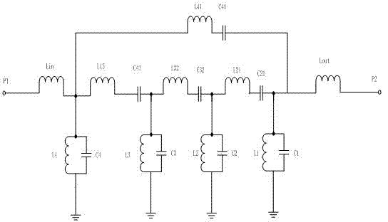
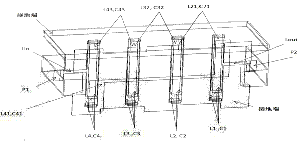
[0016] combine figure 1 , figure 2 and image 3 , the present invention is a C-band low-insertion-loss high-rejection micro-bandpass filter, which includes a surface-mounted 50-ohm impedance input port P1, an input inductance Lin, a first-stage parallel resonance unit L4, C4, a first electromagnetic Coupling circuits L43, C43, second-level parallel resonance units L3, C3, second electromagnetic coupling circuits L32, C32, third-level parallel resonance units L2, C2, third-level electromagnetic coupling circuits L21, C21, fourth-level parallel resonance units L1, C1, fourth electromagnetic coupling circuit L41, C41, output inductor Lout, surface-mounted 50-ohm impedance output port P2 and grounding terminal; surface-mounted 50-ohm impedance input port P1 is connected to input signal at one end, and the other end is connected to input inductor Lin One end o...


PUM


Abstract

The invention relates to a C-band low-insertion-loss and high-rejection miniature band-pass filter which comprises 50-ohm impedance input/output ports, four parallel resonance units, three inter-stage coupling circuits, a zigzag cross coupling circuit and input and output inductors, wherein the 50-ohm impedance input/output ports are arranged on the surface of the band-pass filter, and the structures are all implemented by using a multilayer LTCC (low temperature co-fired ceramic) process technology. The band-pass filter disclosed by the invention has the advantages of good passband selectivity, good out-of-band rejection, low insertion loss, small volume, light weight, high reliability, good electrical properties, good phase frequency characteristics and linearity, good temperature stability, good electrical property batch consistency, low cost, capability of carrying out mass production, and the like. The band-pass filter is especially suitable to be used as a miniature microwave device in aviation, aerospace and radar systems, intelligent weapons for individual soldiers, and airborne and missile-borne wireless systems.

Description

technical field [0001] The invention relates to a filter, in particular to a C-band low insertion loss and high rejection miniature bandpass filter. Background technique [0002] In recent years, the rapid development of the wireless communication industry has urgently required the development of communication systems in the direction of lighter, smaller, more portable, and better performance. As an important device in microwave / radio frequency, the filter has extremely important significance for its high performance, low cost, high reliability and miniaturization. The main technical indicators describing the performance of this component are: passband operating frequency range, stopband frequency range, passband input / output VSWR, passband insertion loss, stopband attenuation, shape factor, insertion phase shift, and time delay Frequency characteristics, temperature stability, volume, weight, reliability, etc. Conventional filter design methods, such as hairpin filter str...

Claims


Application Information

Patent Timeline
IPC IPC(8): H01P1/203H03H7/12
Inventor 戴永胜吴迎春陈建锋范小龙李旭戚湧吴建星韦晨君郭风英韩群飞尹洪浩左同生冯媛谢秋月李平孙宏途汉敏王立杰陈少波徐利周聪张红陈曦於秋杉杨健
Owner CHANGSHU RES INSTITUE OF NANJING UNIV OF SCI & TECH
Why Eureka
Try Eureka