
Method and system for determining optical dispersion displacement optical fiber C band transmission system

A technology of dispersion-shifted optical fiber and transmission system, which is applied to the determination field of dispersion-shifted optical fiber C-band transmission system, can solve the problems of limited use of G.653 optical fiber C-band resources, difficulty in implementation, and difficulty in long-term stable operation, and achieves the total cost of the system. Low cost, convenient and flexible use, and the effect of large transmission bandwidth

Inactive Publication Date: 2004-06-16
HUAWEI TECH CO LTD
View PDF0 Cites 3 Cited by
  • Summary
  • Abstract
  • Description
  • Claims
  • Application Information

AI Technical Summary

Problems solved by technology

However, the wavelength allocation obtained by the completely unequal channel spacing method cannot be compatible with the G.652 and G.655 optical fiber C-band 320G DWDM systems. If the two systems can be integrated and used, a dedicated wavelength division multiplexer / demultiplexer and modification are required. Wavelength conversion devices, and changing amplifier performance parameters, are difficult to implement
At the same time, in the current scheme of completely unequal channel spacing, only the channel spacing reference of the 8-wave DWDM transmission system of G.653 optical fiber is determined, and the system parameter determination method and specific system parameters, such as networking mode and fiber input power Control, etc., the industry has not yet had a solution, and these parameters are very important to the G.653 fiber C-band DWDM transmission system, because in the method of completely unequal channel spacing, due to the particularity of the G.653 fiber, nonlinear The FWM effect, especially the FWM effect, still has an important impact, and it is still difficult to ensure the long-term stable operation of the system. Moreover, the current solution is still very limited in the use of resources in the C-band of G.653 fiber

Method used


Image

  • Method and system for determining optical dispersion displacement optical fiber C band transmission system
  • Method and system for determining optical dispersion displacement optical fiber C band transmission system
  • Method and system for determining optical dispersion displacement optical fiber C band transmission system

Examples


Embodiment Construction

[0028] Because the FWM effect is more serious in the G.653 optical fiber C-band transmission system, this problem must be solved when determining the specific parameters of the G.653 optical fiber C-band transmission system.

[0029] The present invention will be described in further detail below.

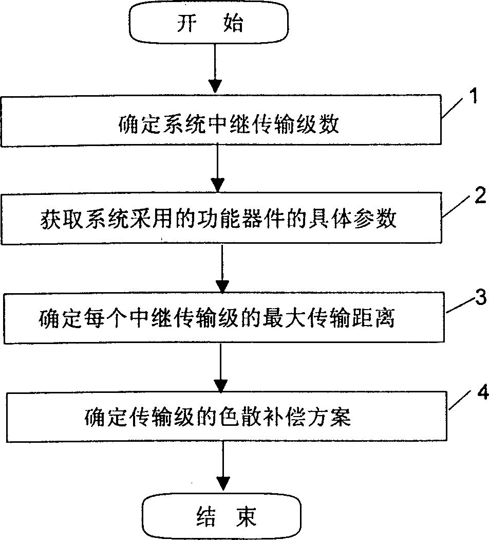
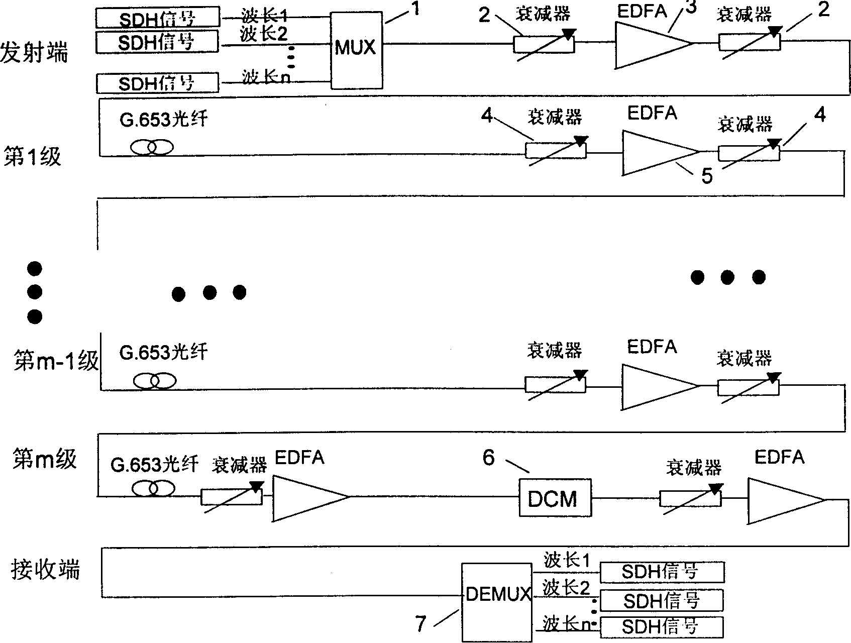
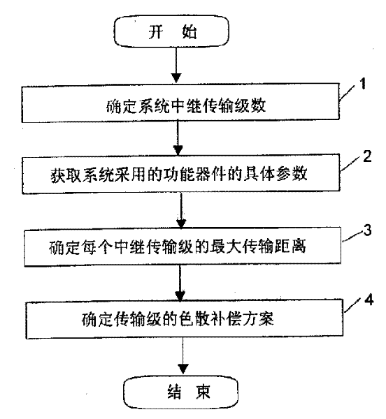
[0030] figure 1 It is a flow chart of the method embodiment of the present invention. according to figure 1 Implement the present invention, at first refer to G.652, G.655 optical fiber C band 320G transmission system standard in step 1 (the purpose of doing like this is in order to be compatible with existing system, avoids existing system to make big change, reduces cost), Determine the number of relay transmission stages of the G.653 optical fiber C-band transmission system. In this example, the number of stages determined is 8. Of course, it can also be other levels, such as 6 levels, 3 levels, and 1 level. Then in step 2, determine the specific parameter characteristics of ...


PUM


Abstract

The invention disclose a conformation method of a kind of dispersion displacement fiber (G.653) band C transmission system, the method confirms the relay transmission series of the system firstly. Then the method uses above relay series to confirm the minimal simplex wave input power and the maximal simplex wave input power of G.653 fiber amplifier, further confirms the maximal transmission distance. Finally, the method confirms proper compensation plan according to the dispersion coefficient and the simplex transmission distance of G.653 fiber. The invention also discloses a system according to above method, which can use the G.653 fiber resources fully.

Description

technical field [0001] The invention relates to a method for determining parameters in an optical communication system, in particular to a method for determining a C-band transmission system of a dispersion-shifted optical fiber (G.653 optical fiber). Background technique [0002] At present, wavelength division multiplexing signals are mainly transmitted by G.652 optical fiber and G.655 optical fiber, and G.653 optical fiber is mainly used for single-wavelength signal transmission due to serious nonlinear effects. With the continuous improvement of wavelength division multiplexing technology, if the G.653 optical fiber is still only used for single-wavelength transmission, a large amount of transmission resources will be wasted. In order to make full use of a large number of G.653 optical fiber resources that have been laid in the world and develop the G.653 optical fiber transmission market, it is of great significance to use G.653 optical fiber to transmit Dense Wavelengt...

Claims


Application Information

Patent Timeline
IPC IPC(8): H04B10/2525
Inventor 马先钟开生
Owner HUAWEI TECH CO LTD
Learn More