High frequency heating apparatus and its control method

a heating apparatus and high frequency technology, applied in the direction of electrical apparatus, ohmic resistance heating, electric/magnetic/electromagnetic heating, etc., can solve the problems of increasing the cost of fabrication cost, bringing about irregular heating or deficiency in heating, and complicated structur

Inactive Publication Date: 2008-04-17
PANASONIC CORP
View PDF8 Cites 49 Cited by
  • Summary
  • Abstract
  • Description
  • Claims
  • Application Information

AI Technical Summary

Benefits of technology

[0043] Therefore, even when a space of installing a wave guide ensured on a side of the upper face of the cavity is set to be equivalent to that of the high frequency heating apparatus of the background art in which the wave guide for 2.45 GHz is installed at the upper face of the cavity by directing the long side horizontally, the wave guide for 5.8 GHz can be mounted to be arranged vertically to direct the long side vertically. Further, by constructing a constitution of mounting to arrange the wave guide vertically in this way, an area occupied by the wave at the upper face of the cavity can be contracted.
[0076] According to the method of controlling the high frequency heating apparatus, when the outputs of the respective high frequency waves exceed the rated power, a total of drive powers for outputting the high frequency waves can be made to be prevented from exceeding the rated power of the high frequency heating apparatus by restricting the output of either one of the high frequency waves.

Problems solved by technology

However, the equipments make a movable part penetrated through a wall portion of the cavity partitioning the heating chamber indispensable, a structure of attaching the movable part onto the cavity for preventing leakage of the electromagnetic wave at the cavity penetrating portion by the movable part is complicated to bring about an increase in cost of fabrication cost by an increase in constituent parts or large-sized formation of the apparatus.
As a result, according to a constitution of oscillating the microwave from a single feeding port into the heating chamber as in the microwave oven of the background art disclosed in Patent Reference 1, mentioned above, when a thickness of the heated object constituting an object of heating is thick, although a surface layer on a side on which the microwave is easy to impinge can sufficiently be heated, with regard to a surface layer on other side and an inner portion of the heated object, there is a concern of bringing about an irregularity in heating or a deficiency in heating.
In this way, according to the high frequency heating apparatus 150 of the background art, in order to carry out heating without irregularity, the turn table 155 and the motor 156 are needed and therefore, the structure is complicated, reliability is deteriorated and cost is increased.
However, the interval of the heating spots is longer than a size of a food stuff to be heated and cooked and therefore, a density of distributing the heating spots which can be present in the food stuff becomes low, the food stuff is partially heated and an irregularity in heating tends to be liable to be produced.
However, whereas according to the high frequency of 5.8 GHz, the density of distributing the heating spots becomes higher than that of the high frequency of 2.45 GHz, a depth thereof of being absorbed to the heated object becomes shallow and therefore, when the heated object is thick-walled, an irregularity in heating in which a surface of the heated object is mainly heated and an inner portion of the heated object is deficient in heating is liable to be brought about.
Therefore, in the case of the high frequency of 5.8 GHz the heating distribution of which becomes dense, although when the heated object is thin-walled, an excellent uniform heating effect can be expected, with regard to the thick-walled heated object, the irregularity in heating is increased in the depth direction, as a result, uniform heating becomes difficult.

Method used


Image

  • High frequency heating apparatus and its control method
  • High frequency heating apparatus and its control method
  • High frequency heating apparatus and its control method

Examples


first embodiment

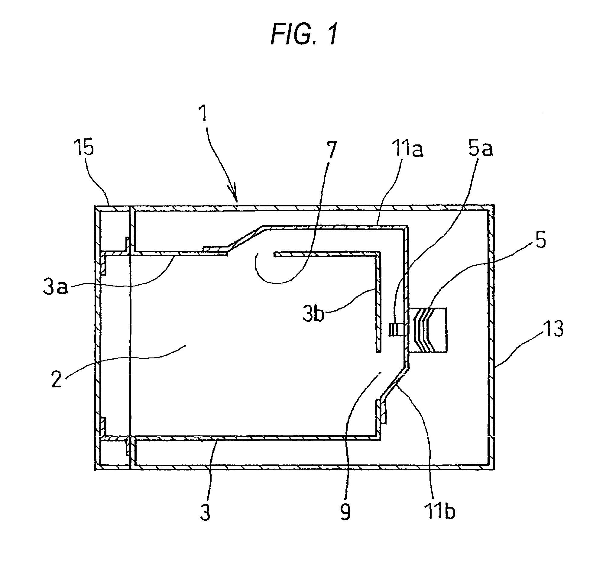
[0110]FIG. 1 is a sectional view according to a high frequency heating apparatus according to the invention.

[0111] The high frequency heating apparatus 1 according to the first embodiment can be used as a household microwave oven and is constructed by a constitution including the cavity 3 for partitioning the heating chamber 2, the magnetron 5 which is high frequency generating means for outputting a microwave of 5.8 GHz from an antenna 5a, a plurality of pieces of the wave guides 11a, 11b respectively having the feeding ports 7, 9 for guiding the microwave outputted from the antenna 5a to emit to the heating chamber 2, the outer shell cabinet 13 for ensuring a space of installing the magnetron 5 and the wave guides 11a, 11b at a surrounding of the cavity 3 by surrounding an outer surrounding of the cavity 3, and the front opening / closing door 15 for opening / closing a front face of the heating chamber 2 for bringing a heated object to and from the heating chamber 2.

[0112]FIG. 1 is ...

second embodiment

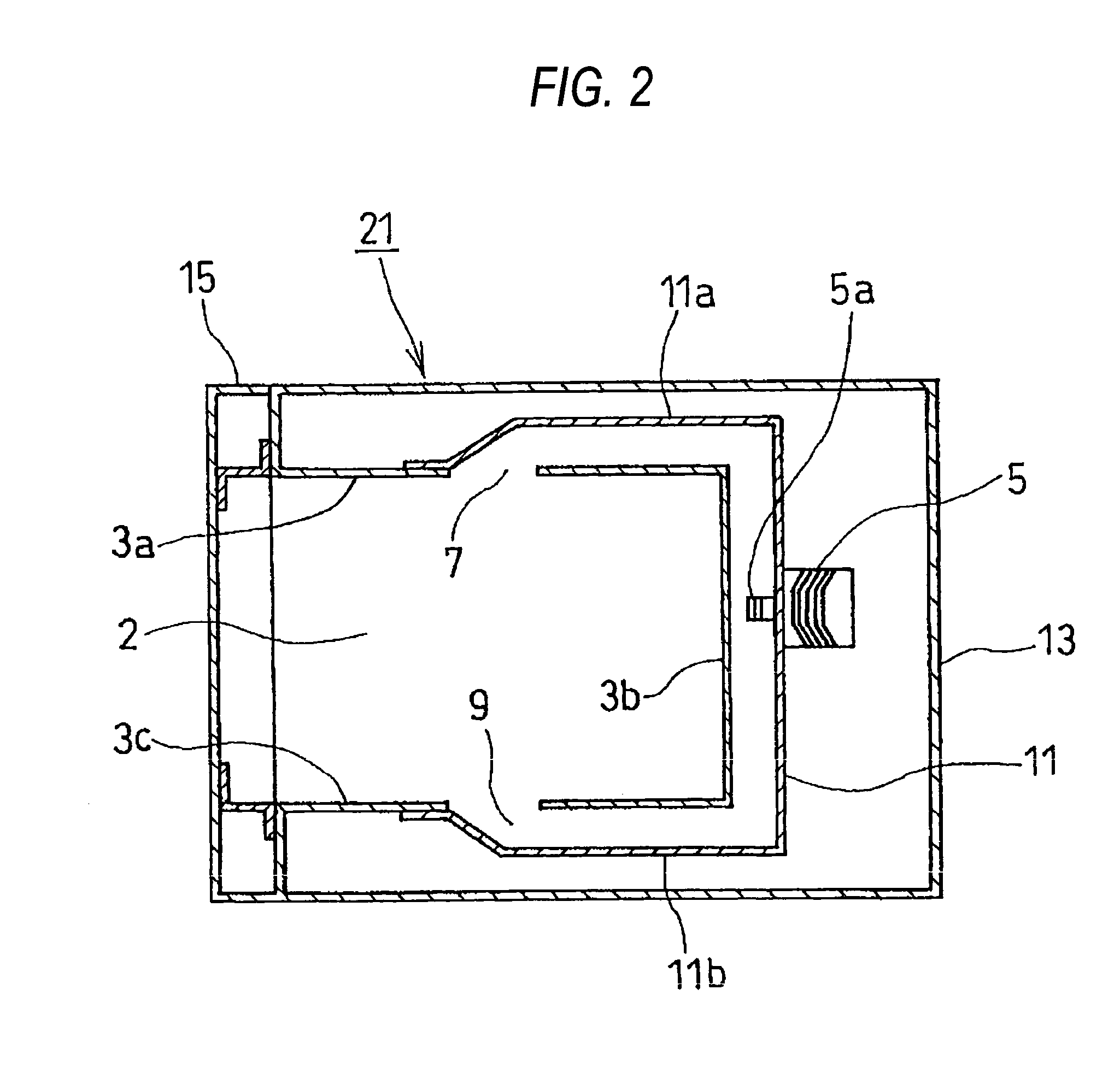
[0119]FIG. 2 is a sectional view of the high frequency heating apparatus according to the invention.

[0120] The high frequency heating apparatus 21 of the second embodiment is constructed by a constitution in which the wave guides 11a, 11b are arranged such that the two feeding ports 7, 9 are opened at upper and lower faces of the heating chamber 2, that is, to be opposed to the upper wall 3a and the bottom wall 3c of the cavity 3, although the first wave guide 11a is the same as that of the first embodiment, the second wave guide 11b is mounted along the bottom wall 3c of the cavity 3 constituting the lower face of the heating chamber 2 by being extended downward from the magnetron 5 and the feeding port 9 is opened at substantially a center of the bottom wall 3c.

[0121] Further, the second embodiment is constructed by the constitution common to that of the first embodiment other than a change in the positions of mounting the feeding ports 7, 9 and a change in shapes of the wave gui...

third embodiment

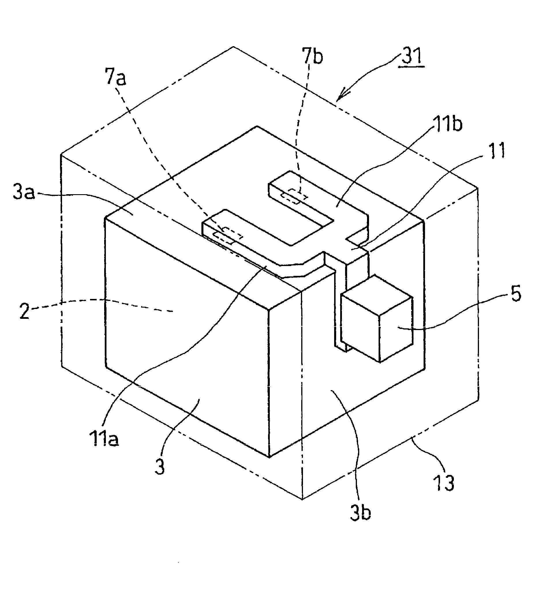
[0123]FIG. 3 is a perspective view of the high frequency heating apparatus according to the invention viewed from a rear side.

[0124] The high frequency heating apparatus 31 of the third embodiment is constructed by a constitution of providing two pieces of the feeding ports 7a, 7b at the upper face of the heating chamber 2 by two pieces of the wave guides 11a, 11b arranged at the upper wall 3a of the cavity 3. Two pieces of the wave guides 11a, 11b are formed by bifurcating a single piece of the common tube 11 extended upward from the magnetron 5.

[0125] According to the constitution, impingement of the microwaves from the upper face to the heated object contained in the heating chamber 2 can uniformly be dispersed over a wide range and it can be expected to considerably increase a heating distribution to the upper face of the heated object.

[0126] Further, by combining a constitution of providing a feeding port at a side face (including rear face) or a bottom face of the heating ch...


PUM


Abstract

A problem of the invention is to provide a high frequency heating apparatus capable of realizing excellent heating without an irregularity in heating even for a thick-walled heated object. In order to resolve the above-described problem, according to a high frequency heating apparatus of the invention, a high frequency heating apparatus 1 for heating a heated object by irradiating a microwave having a frequency of 5.8 GHz to the heated object is constituted by mounting a plurality of pieces of wave guides 11a, 11b having feeding ports 7, 9 for emitting microwaves into a cavity 3 partitioning a heating chamber 2.

Description

TECHNICAL FIELD [0001] The present invention relates to a high frequency heating apparatus for heating an object to be heated by supplying a high frequency wave to a heating chamber containing the object and its control method. BACKGROUND ART [0002] A high frequency apparatus having high frequency generating means (magnetron) for outputting a microwave into a heating chamber accommodating an object to be heated has rapidly been spread as a microwave oven which is a heating cooking apparatus of a foodstuff or the like since the object in the heating chamber can be heated in a short period of time and efficiently. [0003] Meanwhile, according to the microwave oscillated into the heating chamber, when there is not electromagnetic wave stirring means in the heating chamber, a standing wave is formed by reflection at an inner wall face of a cavity partitioning the heating chamber and heating spots are produced at intervals of about a half of a wavelength of the standing wave. [0004] In th...

Claims


Application Information

Patent Timeline
Patent Type & Authority Applications(United States)
IPC IPC(8): H05B6/64H05B6/68H05B6/72H05B6/70H05B6/74H05B6/80
CPCH05B6/6402H05B6/707H05B6/708H05B2206/044H05B6/763H05B6/80H05B6/745
Inventor TAKIZAKI, TAKESHINOBUE, TOMOTAKASAKAMOTO, KAZUHOMIHARA, MAKOTO
Owner PANASONIC CORP
Why Eureka
Try Eureka