Analogue Electronic Clock and Motor Control Circuit

an electronic clock and digital technology, applied in the direction of motor/generator/converter stopper, dynamo-electric converter control, generating/distributing signals, etc., can solve the problem of increasing power consumption, complicated circuit constitution, and inability to reduce the size of ic chips

Active Publication Date: 2008-04-17
SEIKO INSTR INC
View PDF4 Cites 34 Cited by
  • Summary
  • Abstract
  • Description
  • Claims
  • Application Information

AI Technical Summary

Benefits of technology

[0016] According to the present invention, there is provided a motor control circuit which includes: a rotation detection means which detects a rotation detection signal in response to a rotation of a motor and detects whether the motor is rotated or not based on the rotation detection signal; and a control means which selects a main drive pulse corresponding to a magnitude of a load of the motor out of a plurality of ma...

Problems solved by technology

Accordingly, the counter circuit is necessary in the analogue electronic clock and hence, in an attempt to form only an electronic circuit which constitutes a motor control circuit or an electronic circuit which constitutes an electronic clock including the motor control circuit into an integrated circuit (IC), there exists a drawback that an IC chip size cannot be reduced.
Further, the pulse width to be changed, the pulse-width changing timing and the like in performing the pulse-down differ for respective products and hence, there exists a drawback that the circuit constit...

Method used


Image

  • Analogue Electronic Clock and Motor Control Circuit
  • Analogue Electronic Clock and Motor Control Circuit
  • Analogue Electronic Clock and Motor Control Circuit

Examples


Embodiment Construction

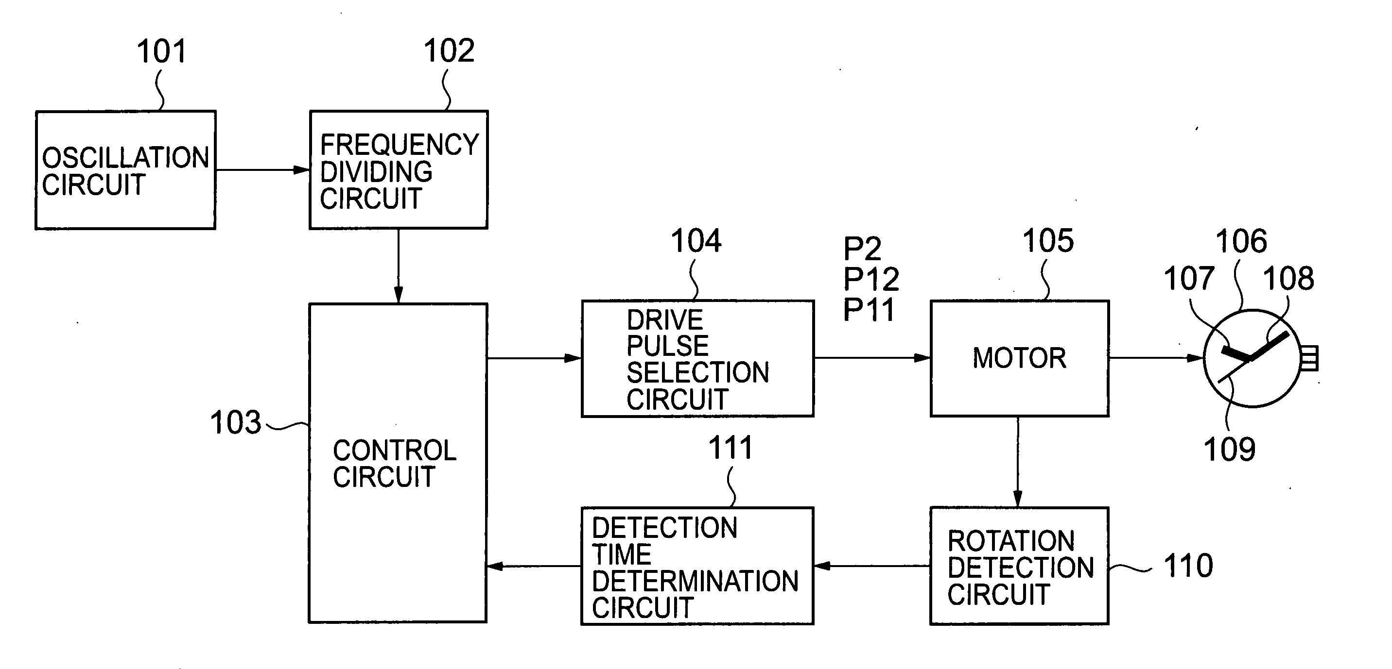
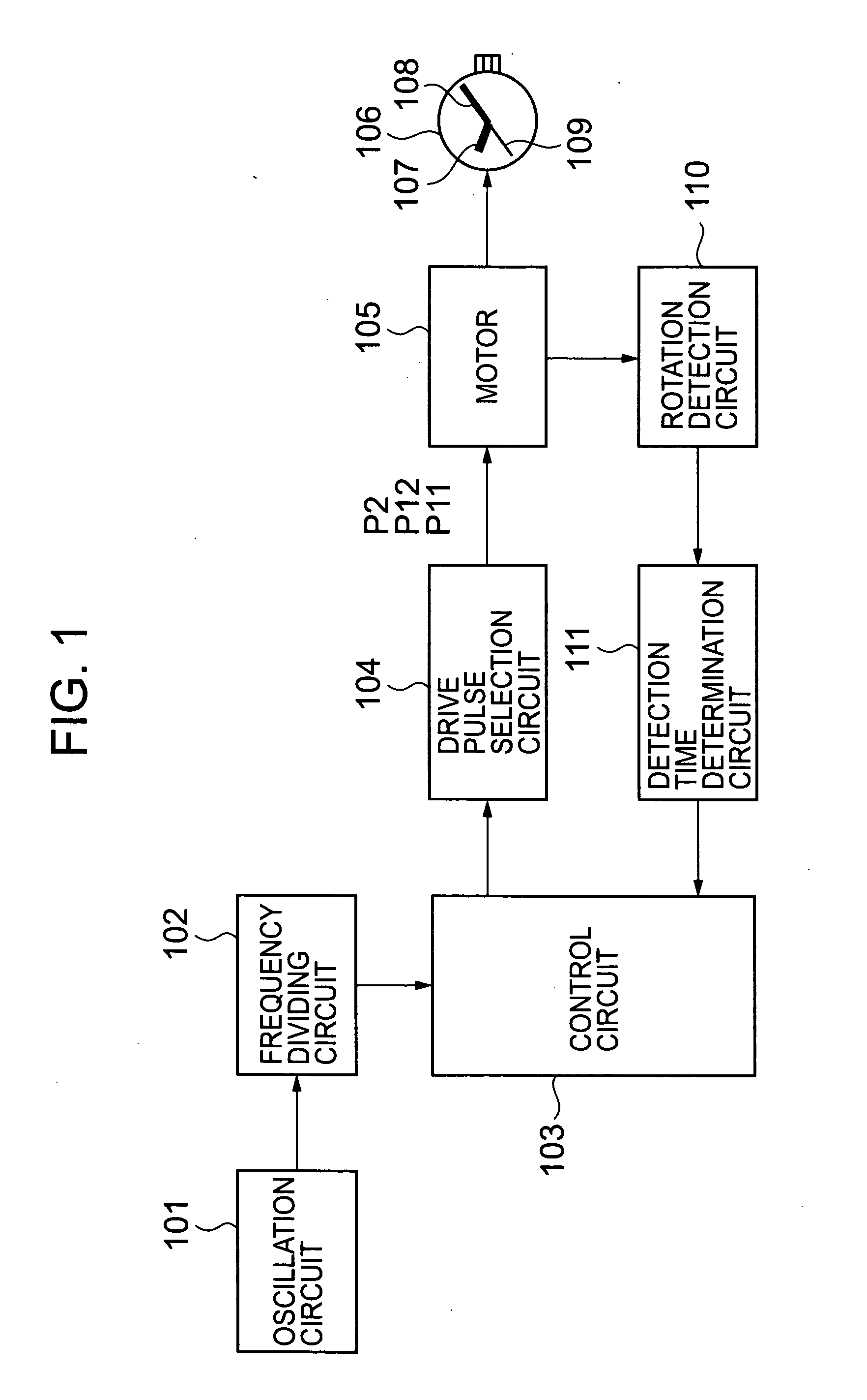
[0058]FIG. 1 is a block diagram of an analogue electronic clock according to an embodiment of the present invention and shows an example of an analogue electronic wrist watch.

[0059] In FIG. 1, the electronic clock includes an oscillation circuit 101 which oscillates a signal of a predetermined frequency, a frequency dividing circuit 102 which generates clock signals which become references at the time of timer counting by dividing a signal generated by the oscillation circuit 101, a control circuit 103 which performs controls such as a control of respective electronic circuit components which constitute the electronic clock, a change control of drive pulses and the like, a drive pulse selection circuit 104 which selects and outputs a drive pulse for motor rotational driving based on a control signal from the control circuit 103, a motor 105 which is rotationally driven based on the drive pulse from the drive pulse selection circuit 104, an analogue display part 106 which includes t...


PUM


Abstract

No counter circuit is used but a simple arrangement is used to allow a motor to be rotation driven by main drive pulses in accordance with a load. A control circuit (103), after starting to use second main drive pulses to drive a motor (105), continues the rotation driving of the motor (105) by use of the second main drive pulses if a rotation detecting circuit (110) detects a rotation detection signal indicative of the rotation of the motor (105) after a passage of a predetermined reference time period. However, the control circuit (103) uses first main drive pulses, which are shorter in pulse width than the second main drive pulses, instead of using the second main drive pulses, to perform the rotation driving of the motor (105) if the rotation detection signal is detected before the passage of the reference time period. Alternatively, the control circuit (103) uses correction drive pulses, which are the longest in pulse width, to perform a forced rotation driving of the motor (105) if no rotation detection signal is detected. Thereafter, the control circuit (103) uses the first main drive pulses to perform the rotation driving of the motor.

Description

BACKGROUND OF THE INVENTION [0001] 1. Field of the Invention [0002] The present invention relates to an analogue electronic clock and a motor control circuit which is suitably applicable to an analogue electronic clock or the like. [0003] 2. Description of the Prior Art [0004] Conventionally, an analogue electronic clock which is configured to rotationally drive time hands for displaying time such as a hour hand, a minute hand and the like using a motor has been used. The analogue electronic clock includes the motor which rotationally drives the time hands and a motor control circuit which controls the rotation of the motor, wherein by rotationally driving the motor by the motor control circuit based on time signals which constitute references of time, the time hands can perform a time display. [0005] In the electronic clock which is described in JP-B-61-15385, for rotationally driving the motor which serves to drive the time hands, the motor is rotationally driven by selectively us...

Claims


Application Information

Patent Timeline
IPC IPC(8): G04B17/20H02P31/00G04C3/14H02P8/02
CPCH02P8/02G04C3/143
Inventor MANAKA, SABUROOGASAWARA, KENJI
Owner SEIKO INSTR INC
Why Eureka
Try Eureka