Multi-chassis emulated switch

a multi-chassis, switch technology, applied in the field of computer networking, can solve problems such as encountering problems and eliminating the possibility of load sharing

Active Publication Date: 2008-04-17
CISCO TECH INC
View PDF7 Cites 38 Cited by
  • Summary
  • Abstract
  • Description
  • Claims
  • Application Information

AI Technical Summary

Problems solved by technology

Data center managers face several challenges in fulfilling these goals.
The network design depicted in FIG. 2, however, encounters a problem

Method used


Image

  • Multi-chassis emulated switch
  • Multi-chassis emulated switch
  • Multi-chassis emulated switch

Examples


example embodiments

[0022]In this application, numerous specific details are set forth in order to provide a thorough understanding of the present invention. It will be obvious, however, to one skilled in the art, that the present invention may be practiced without some or all of these specific details. In other instances, well known process steps have not been described in detail in order to not obscure the present invention.

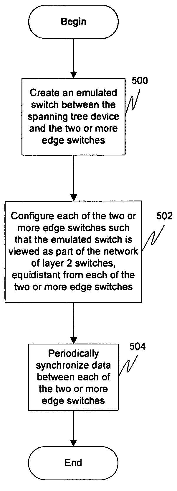
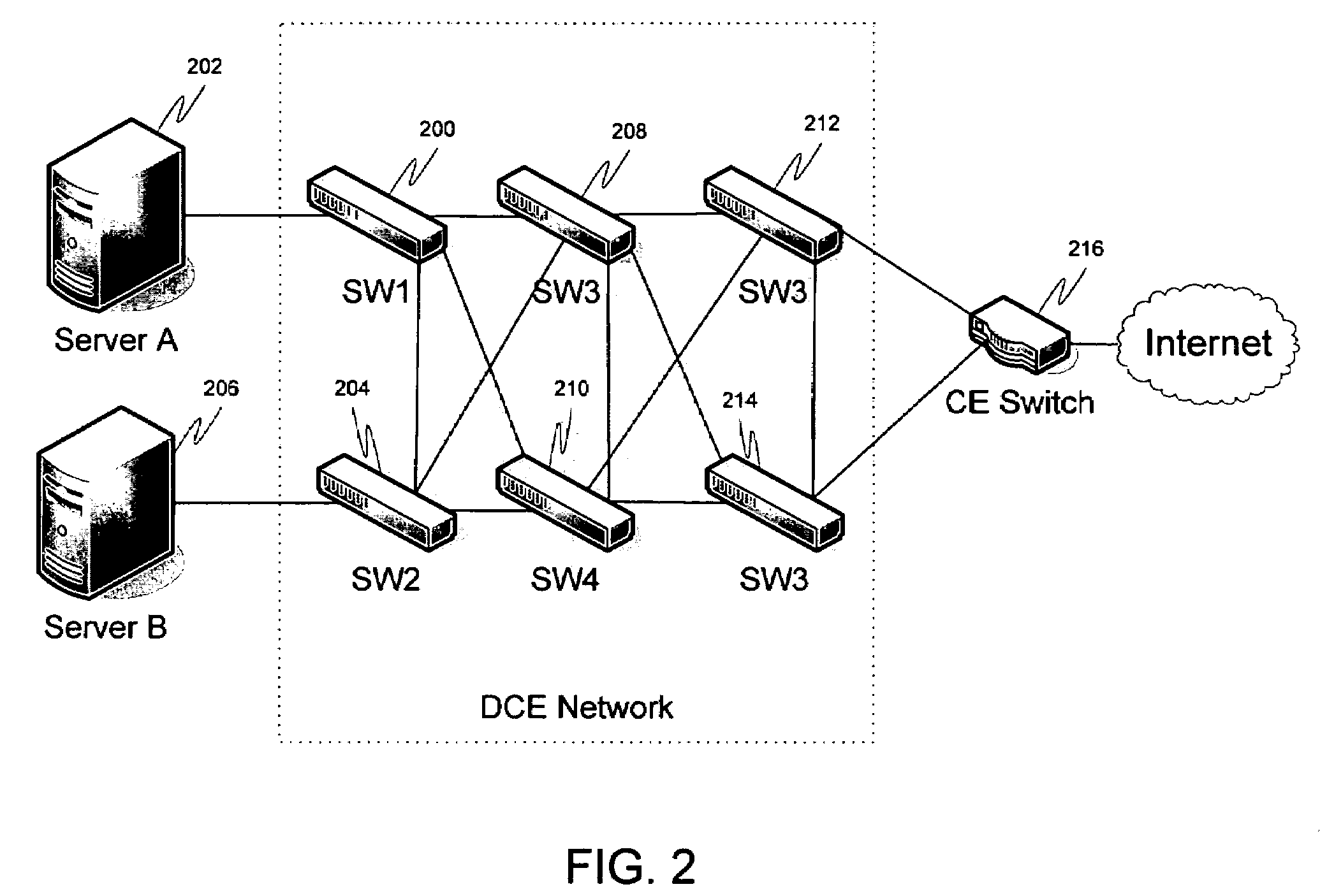
[0023]A solution is provided wherein the interfaces between multiple chassis (e.g., edge switches) and non-DCE devices are treated as a single emulated switch. This emulated switch effectively enables 2 different views to the 2 different sides. FIG. 3 illustrates an example network of layer 2 switches including an emulated switch. Here, emulated switch 300 is viewed as being between edge switches 302, 304 and the CE device 306. It appears to be equidistant from each of the edge switches 302, 304. For the CE-side, it appears that the multiple links are actually a single port bundle...


PUM


Abstract

A solution is provided wherein the interfaces between multiple chassis (e.g., edge switches) in a network of layer 2 devices and a spanning tree device are treated as a single emulated switch. This emulated switch effectively enables two different views to the two different sides. Thus, frames from the network of layer 2 switches destined to any port of the emulated switch may take any of the links (through any of the physical switches), thereby enabling effective load-balancing for frames traveling from the layer 2 network side into the spanning tree device. Meanwhile the spanning tree device does not recognize an illegal loop in its connection to two different edge switches as it views the two links as a single logical EtherChannel.

Description

BACKGROUND OF THE INVENTION[0001]1. Technical Field[0002]The present invention relates to computer networking.[0003]2. Description of the Related Art[0004]Data management within organizations is an ever increasing concern, especially with the rise of the Internet information age. The heart of this data management function is sometimes known as a data center. Over the last decade, data centers have evolved into the strategic focus of Information Technology (IT) efforts to protect, optimize, and grow the organization.[0005]Data center managers face several challenges in fulfilling these goals. Most enterprise data centers grew rapidly to meet the explosive economic growth of recent times. Consequently, applications commonly stand alone in underutilized, isolated infrastructure silos. Each infrastructure silo is designed based on the inclination of the specific application being deployed, so that a typical data center supports a broad I assortment of operating systems, computing platfo...

Claims


Application Information

Patent Timeline
IPC IPC(8): H04L12/28H04L45/243H04L45/586
CPCH04L12/462H04L45/00H04L45/245H04L49/70H04L45/586H04L47/125H04L49/351H04L45/48
Inventor SANE, SANJAYKREEGER, LAWRENCEEDSALL, THOMASGANESAN, ELANGOHANG, SOEI-SHINMELLACHERUVU, RAMANA
Owner CISCO TECH INC
Why Eureka
Try Eureka