
Connector

a technology of connecting rods and connectors, applied in the direction of coupling device connection, engagement/disengagement of coupling parts, electrical apparatus, etc., can solve the problems of affecting the sealing performance the connection used near the engine of the car is subject to vibration, and the sealing ring cannot prevent shaking. , to achieve the effect of preventing the shaking of the seal ring and improving the sealing performan

Inactive Publication Date: 2008-04-24
SUMITOMO WIRING SYST LTD
View PDF10 Cites 6 Cited by
  • Summary
  • Abstract
  • Description
  • Claims
  • Application Information

AI Technical Summary

Benefits of technology

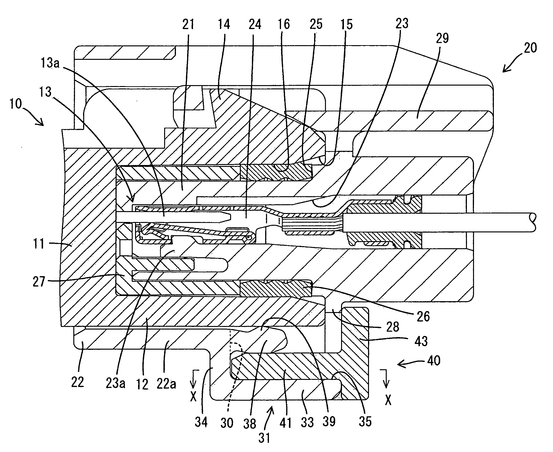
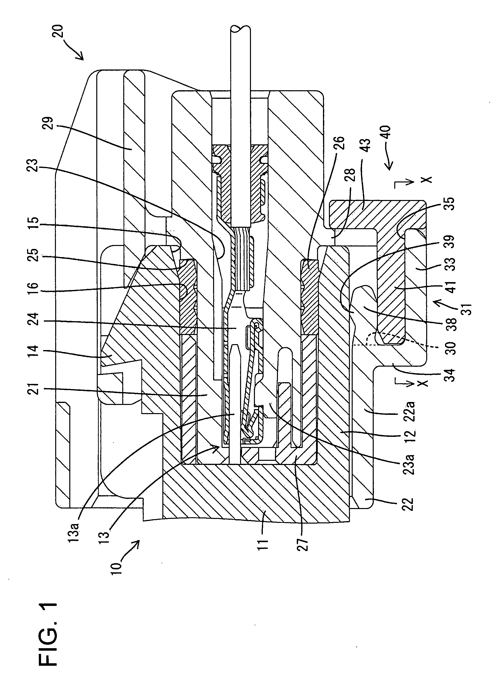
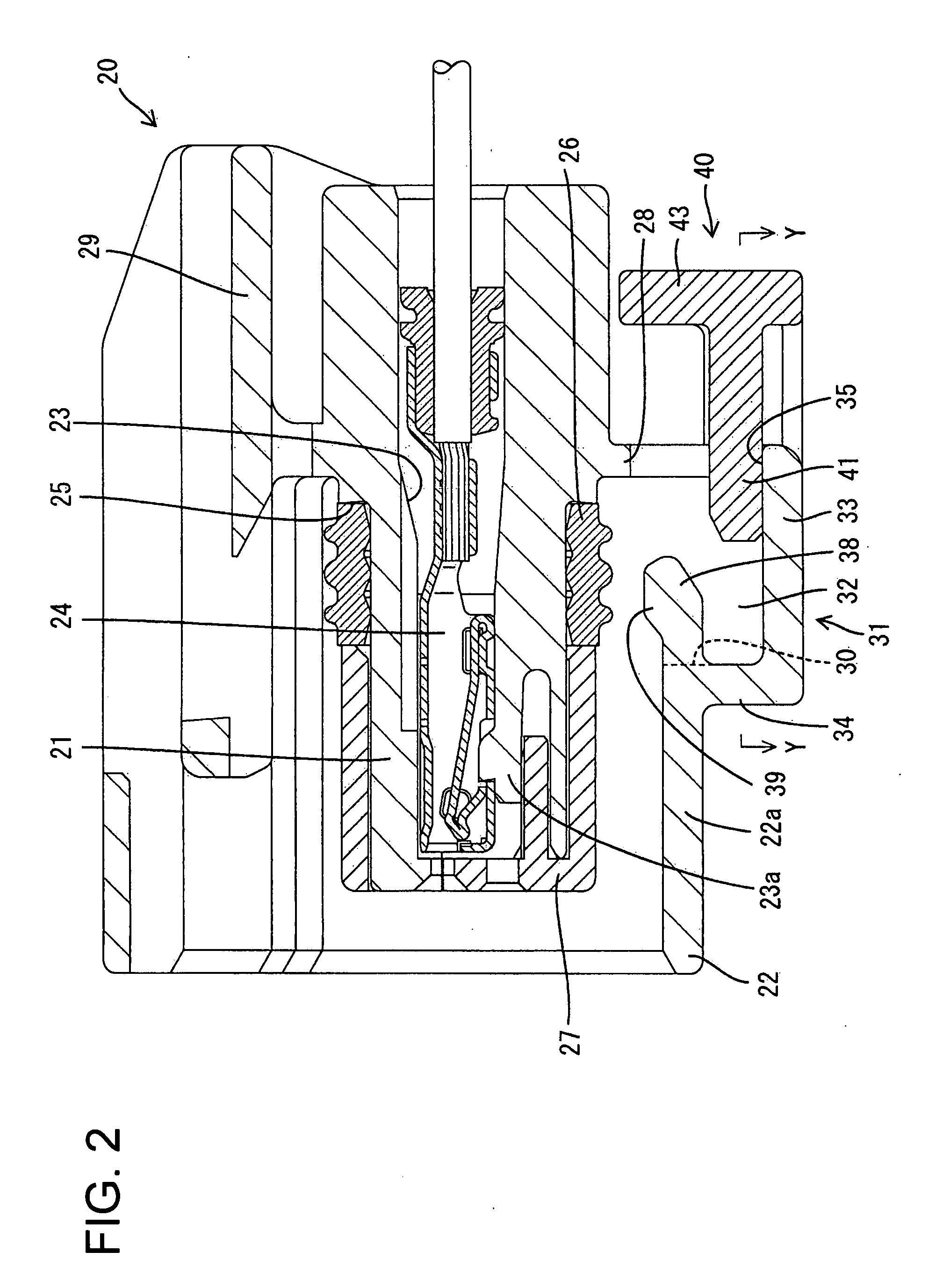
The invention is a connector made of synthetic resin, consisting of a male housing and a female housing. The male housing has a hood, and the female housing can fit into the hood. The male and female housings have an elastic hold-down piece that contacts the mating housing perpendicularly or approximately perpendicularly. A retainer prevents the elastic hold-down piece from being displaced. A rubber seal ring is mounted between the male and female housings when they are fit together. The elastic hold-down piece prevents the housings from shaking in directions angularly aligned to the fit-in direction. The elastic hold-down piece is more effective at preventing the housings from shaking than an elastic hold-down piece made of rubber. The retainer ensures the elastic hold-down piece securely displays its hold-down function. The elastic pressing force of the elastic hold-down piece is imparted to the seal ring through the mating housing. This improves the sealing performance of the seal ring.

Problems solved by technology

A connector used near the engine of a car is subjected to vibration, and shaking occurs between a male housing and a female housing in a direction approximately perpendicular to the direction in which the male and female housings fit together.
There is a fear that the shaking causes a slight sliding-contact wear to be generated between terminal fittings inside both housings.
Thus, the seal ring cannot prevent shaking.

Method used


Image

  • Connector
  • Connector
  • Connector

Examples


Embodiment Construction

[0022]A connector in accordance with the invention includes a male housing identified by the numeral 10 in FIGS. 1 and 2. The male housing 10 is made of synthetic resin and has a housing body 11 for holding male terminal fittings 13. A hood 12 projects forward from the housing 11 and is formed integrally with the housing 11. A long and narrow tab 13a is insert molded in the housing body 11 or is press-fit in the housing body 11 and projects from a front-end surface of the housing body 11. Thus, the housing body 11 is surrounded by the hood 12. The hood 12 is oblong in a front view and a locking projection 14 is formed on an outer surface of an upper wall of the hood 12. The entire inner peripheral surface of a front end of the hood 12 is cut out along an edge of an opening of the hood part 12 to form a guide surface 15. A sealing surface 16 is formed on an inner peripheral surface of the front end of the hood 12 adjacent to a rear side of the guide surface 15.

[0023]The connector als...


PUM


Abstract

A connector has a male housing (10) with a hood (12) and a female housing (20) that can be telescoped into the hood (12). The female housing (20) has an elastic hold-down piece (38) that elastically contacts the male housing (10) at an angle to a direction in which the housings (10; 20) are telescoped together. An elastic pressing force of the elastic hold-down piece (38) prevents housings (10) and (20) from shaking at an angle to the fit-in direction. The elastic hold-down piece (38) is made of the synthetic resin and has a small elastic deformation amount. Thus, the elastic hold-down piece (38) has a higher effect than an elastic hold-down piece made of rubber in preventing shaking.

Description

BACKGROUND OF THE INVENTION[0001]1. Field of the Invention[0002]The invention relates to a connector.[0003]2. Description of the Related Art[0004]A connector used near the engine of a car is subjected to vibration, and shaking occurs between a male housing and a female housing in a direction approximately perpendicular to the direction in which the male and female housings fit together. There is a fear that the shaking causes a slight sliding-contact wear to be generated between terminal fittings inside both housings.[0005]U.S. Pat. No. 6,685,496 uses a seal of the connector to overcome the generation of the slight sliding-contact wear. More particularly, a rubber seal ring is mounted on the periphery of the female housing and closely contacts the inner periphery of the hood of the male housing when both housings have been fit together. U.S. Pat. No. 6,685,496 explains that the seal ring prevents shaking between the male and female housings in a direction perpendicular to the direct...

Claims


Application Information

Patent Timeline
Patent Type & Authority Applications(United States)
IPC IPC(8): H01R13/62
CPCH01R13/639H01R13/627
Inventor HIRAMATSU, HIROYUKI
Owner SUMITOMO WIRING SYST LTD
Learn More