Sound Attenuation Enclosure

Inactive Publication Date: 2008-05-01
SOUND SEAL
View PDF9 Cites 15 Cited by
  • Summary
  • Abstract
  • Description
  • Claims
  • Application Information

AI Technical Summary

Benefits of technology

[0007]In another embodiment each of the plurality of panels has an inner enclosed chamber filled with a sound retardant material. The panels are supported side by side so that each panel is positioned in spaced relation to an adjacent panel, and the plurality of panels are arranged to form an enclosure. In addition, the panels are arranged so that a top section or bottom section of each panel overlaps a top section or bottom section of an adjacent panel. The overlapping of the panels provides an additional barrier to emanating sound pressure waves, as opposed when panels are aligned side by side but are not overlapping. A surface of the panels that form an inner surface of the enclosure may comprise a series of adjacent cavities and protrusions, which cause viscous losses as sound pressure waves move in and out of the cavities. In addition, or alternatively the inner surface of the enclosure may be lined with sound attenuating materials that form a textured service to have the same effect as the series of cavities on sound pressure waves.
[0008]The enclosure, and components of the enclosu

Problems solved by technology

A surface of the panels that form an inner surface of the enclosure may comprise a series of adjacent cav

Method used


Image

  • Sound Attenuation Enclosure
  • Sound Attenuation Enclosure
  • Sound Attenuation Enclosure

Examples


Example

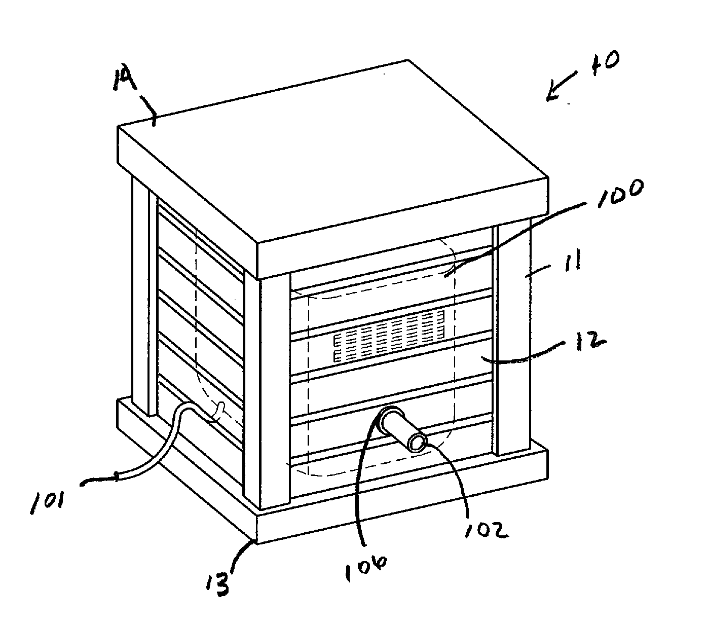
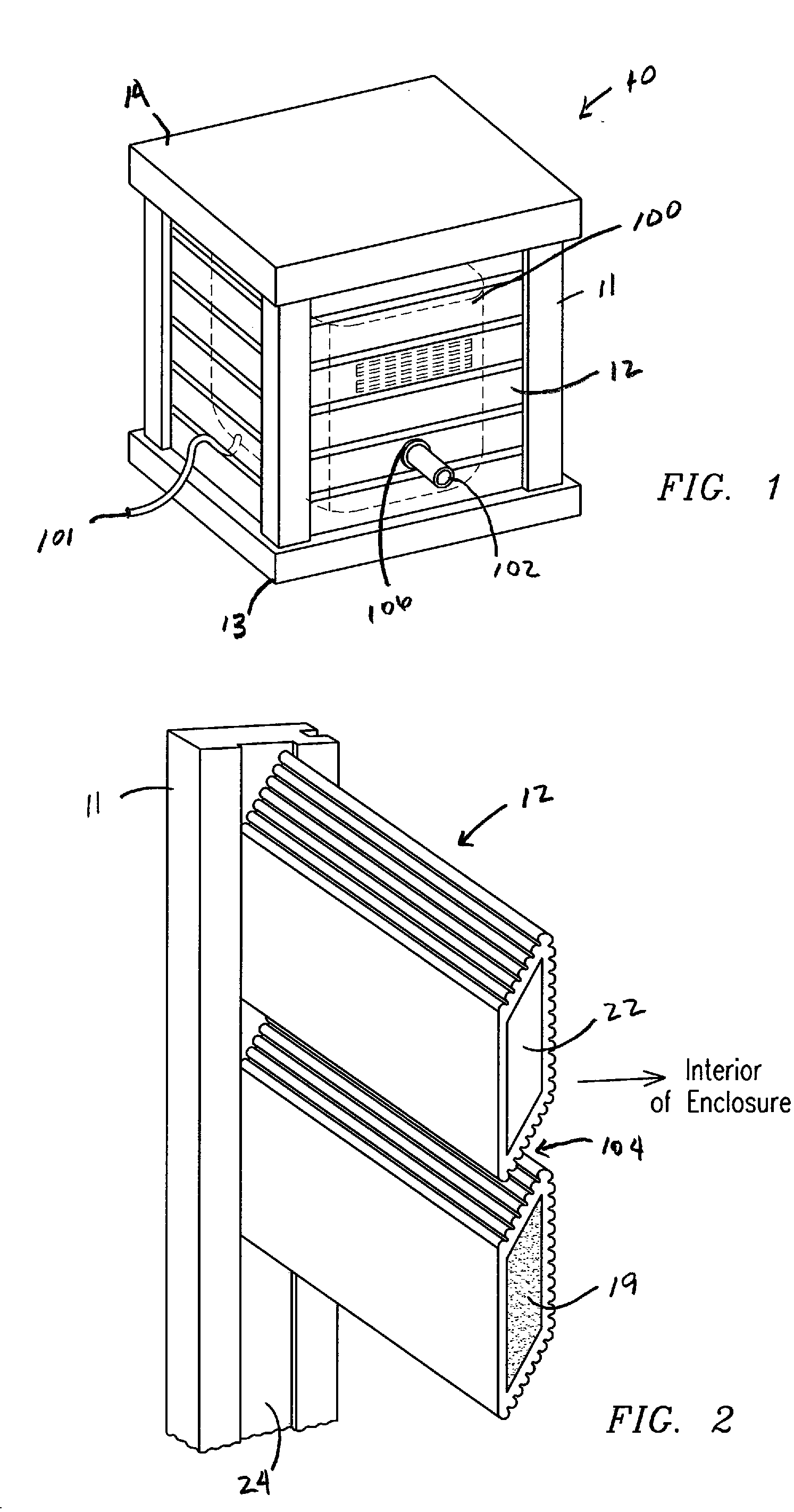
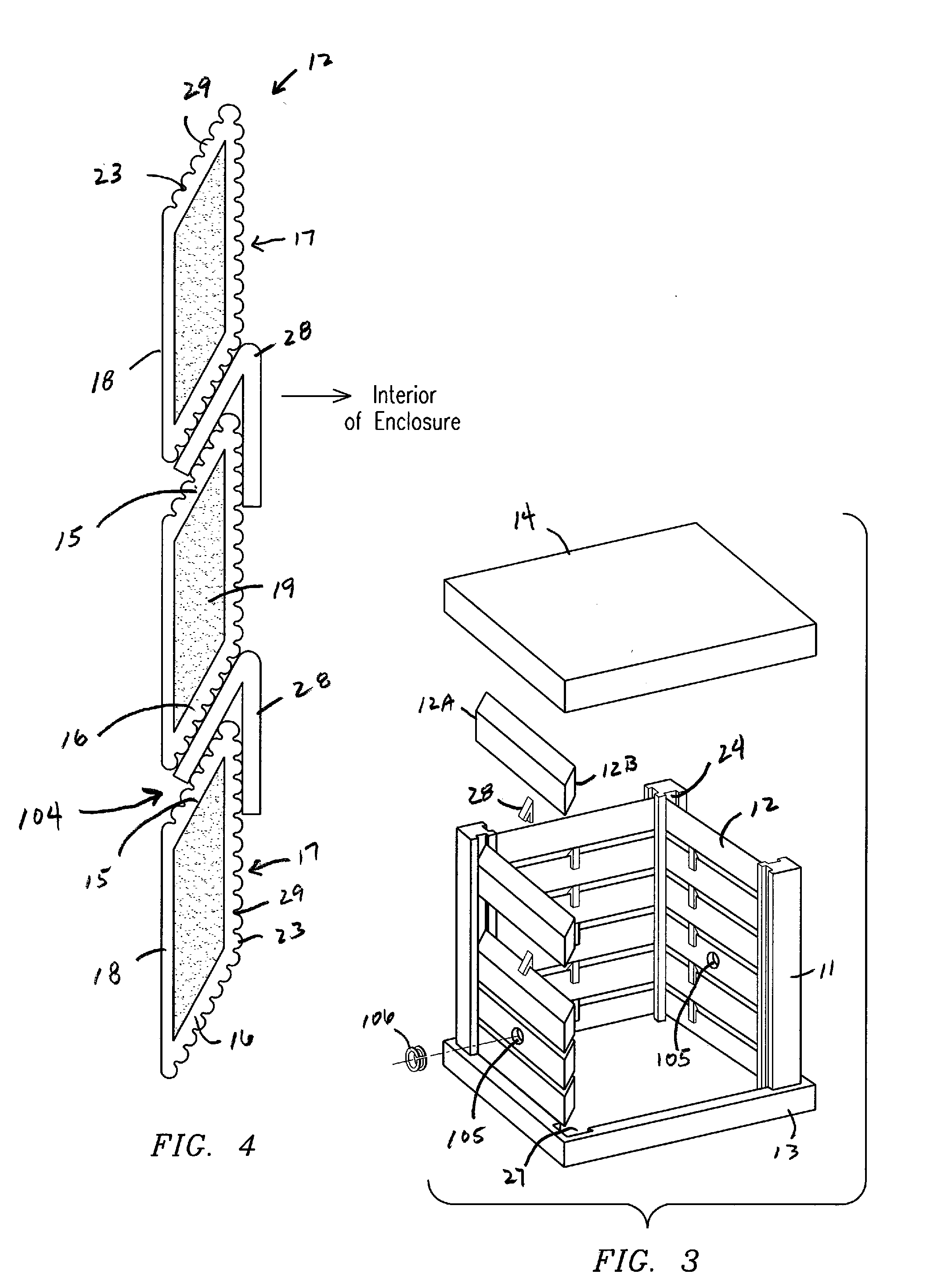
[0033]A first embodiment of the present invention for a sound attenuation enclosure is illustrated in FIGS. 1 through 4. The enclosure 10 comprises a plurality of sound insulating panels 12 attached to and supported on support columns 11. One or more of the panels 12 has a shell-like, or tubular, configuration having an inner chamber 22 filled with a sound retardant material 19. The columns 11 may also have a similar configuration for retaining the sound retardant material 19.

[0034]Various sound retardant materials are acceptable, including, but not limited to, rubber, polymer foam, water, gravel, sand, or other dense materials used for sound attenuation. In some instances, the panels 12 and / or columns 11 may not contain the sound retardant material, and the components remain hollow. Alternatively, the panels 12 may be fabricated as a solid piece of sound retardant material, and not have a chamber 22.

[0035]The panels 12 and columns 11, and those similar components described in all e...

Example

[0049]A second embodiment of the enclosure 10 illustrated in FIGS. 5, 6 and 7, includes panels 32 supported in spaced relation to one another by columns 31. The panels 32 include a first set 32A and a second set 32B spaced laterally from the first set 32A toward an exterior of the enclosure. In each set 32A and 32B, adjacent panels 32 are spaced apart forming a gap 33 between consecutive panels 32. However, the panels 32 in the first set 32A are positioned with respect to the panels 32 of the second set 32B so that the first set 32A covers at least a portion of the gaps 33 between consecutive panels 32 in the second set 32B. Similarly, the second set 32B is positioned with respect to the first set of panels 32A so that second set of panels 32B covers at least a portion of the gaps 33 between consecutive panels in the second set 32B.

[0050]The panels 32 shown in FIG. 7 have the inclined sections 15 and 16 as in the above-described first embodiment. However, other shapes may be used. F...

Example

[0054]A third embodiment of the enclosure is illustrated in FIGS. 8A, 8B, 9 and 10, also includes a similar “staggered” panel configuration as in the second embodiment; however, columns are not necessary to arrange the panels to form an enclosure. More specifically, the enclosure 10 includes panels 41 including a first set of panels 41A and a second set of panels 41B. The first set of panels 41A includes a plurality panels that are spaced apart forming a gap 43 between each consecutive pair of panels 41. The second set of panels 41B are laterally spaced from the first set of panels 41A toward an exterior of the enclosure 40. Panels from the first set 41A cover at least a portion of the gaps 43 between the panels of the second set 41B; and, panels from the second set 41B cover at least a portion of the gaps 43 between the panels of the first set 41A.

[0055]As shown in FIG. 9, the panels of the first set 41A and second set 41B are the same length. Two notches 44 are formed in each pane...


PUM


Abstract

A sound attenuation enclosure comprising a plurality of panels positioned side by side one another forming an enclosure about an operating device that generates noise. The panels are supported by a plurality of columns, and are separable from the columns so the enclosure and its components are transportable. The panels and columns may have an enclosed inner chamber filled with a sound retardant material.

Description

FIELD OF THE INVENTION[0001]This invention relates to devices used to attenuate sound emanating from mechanical or electromechanical operating systems where noise, sound or vibration are a consideration for the operation of such systems.BACKGROUND OF THE INVENTION[0002]An ongoing problem associated with mechanical and electro-mechanical operating systems is the level of noise such systems generate. With the continuous technical advances in the fields of metallurgy, electrical and mechanical engineering, manufacturers of equipment are able to minimize the physical dimensions of equipment including the thickness and mass of equipment components. Sound and improved efficiency / performance often cause conflicting results. These changes often result in increased noise pollution levels. Examples of such operating systems include, but are not limited to, HVAC units, pool pumps, gas manifolds, emergency storm generators and sump pumps.[0003]Equipment manufacturers often are limited to instal...

Claims


Application Information

Patent Timeline
IPC IPC(8): E04F19/00E04H14/00
CPCE04B1/8218
Inventor SEEL, ROBERT VAUGHAN
Owner SOUND SEAL
Why Eureka
Try Eureka