Image-Forming Apparatus

Active Publication Date: 2008-05-01
BROTHER KOGYO KK
View PDF4 Cites 6 Cited by
  • Summary
  • Abstract
  • Description
  • Claims
  • Application Information

AI Technical Summary

Benefits of technology

[0112]The effect of the configuration of the present embodiment will next be described with reference to the drawings.
[0113]Referring to FIG. 1, in the present embodiment, a near end portion of the first side support portion 213 is located just under the first upper corner portion 314. A near end portion of the second side support portion 215 is offset from the second lower corner portion 216 such that the second upper corner portion 315 projects beyond the near end portion of the second side support portion 215. The amount of offset is a minimum amount where a standard user can easily hook his/her hand onto the corner portion of the image scanner section 3.
[0114]That is, in the present embodiment, in a region between the second lower corner portion 216, and the second upp

Problems solved by technology

However, such a configuration may involve unstable support of the image-reading section, potentially resulting in failure in im

Method used


Image

  • Image-Forming Apparatus
  • Image-Forming Apparatus
  • Image-Forming Apparatus

Examples


Embodiment Construction

[0043]An embodiment of the present invention (the best mode contemplated at the time of filing the present application) will next be described in detail with reference to the drawings.

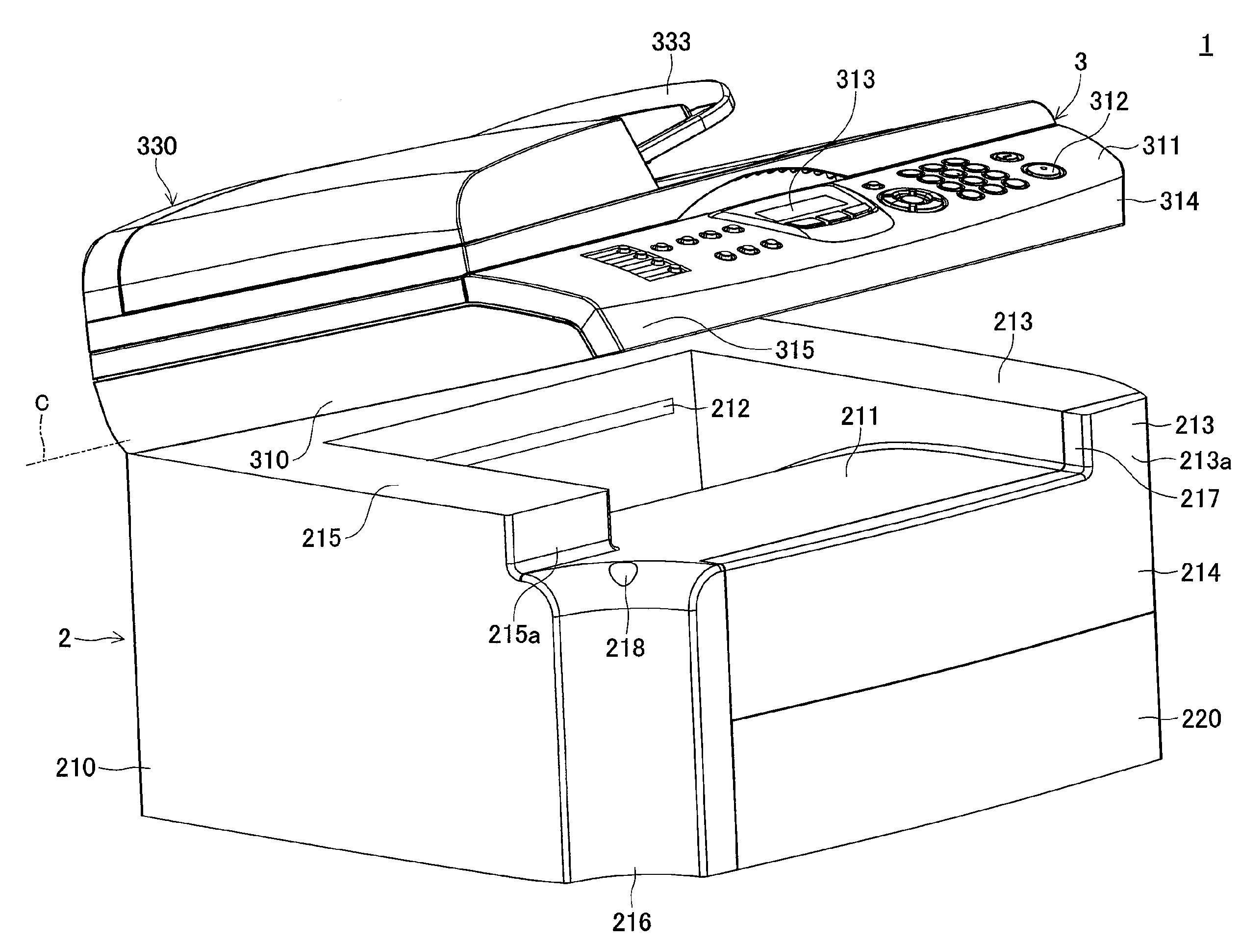
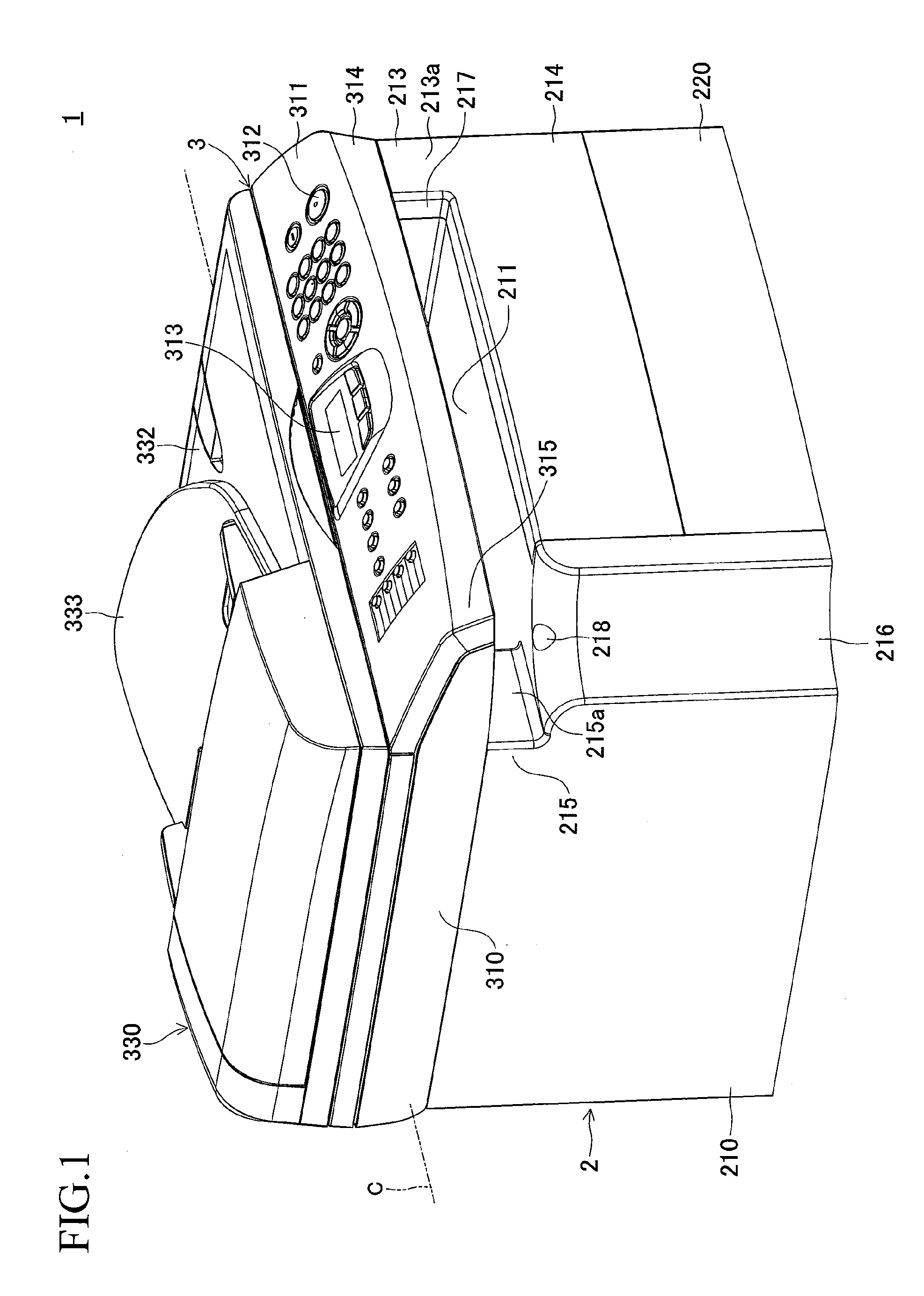
[0044]FIG. 1 is a perspective view of a multifunction printer 1 which is an embodiment of an image-forming apparatus according to the present invention. The multifunction printer 1 can read an image formed on a sheet of recording medium of up to A4 size (210 mm width×297 mm length). Also, the multifunction printer 1 can form an image on a sheet of recording medium of up to A4 size.

[0045]Referring to FIG. 1, the multifunction printer 1 includes a printer section 2, which serves as the image-forming section of the present invention, and an image scanner section 3, which serves as the image-reading section of the present invention. The image scanner section 3 is disposed above the printer section 2.

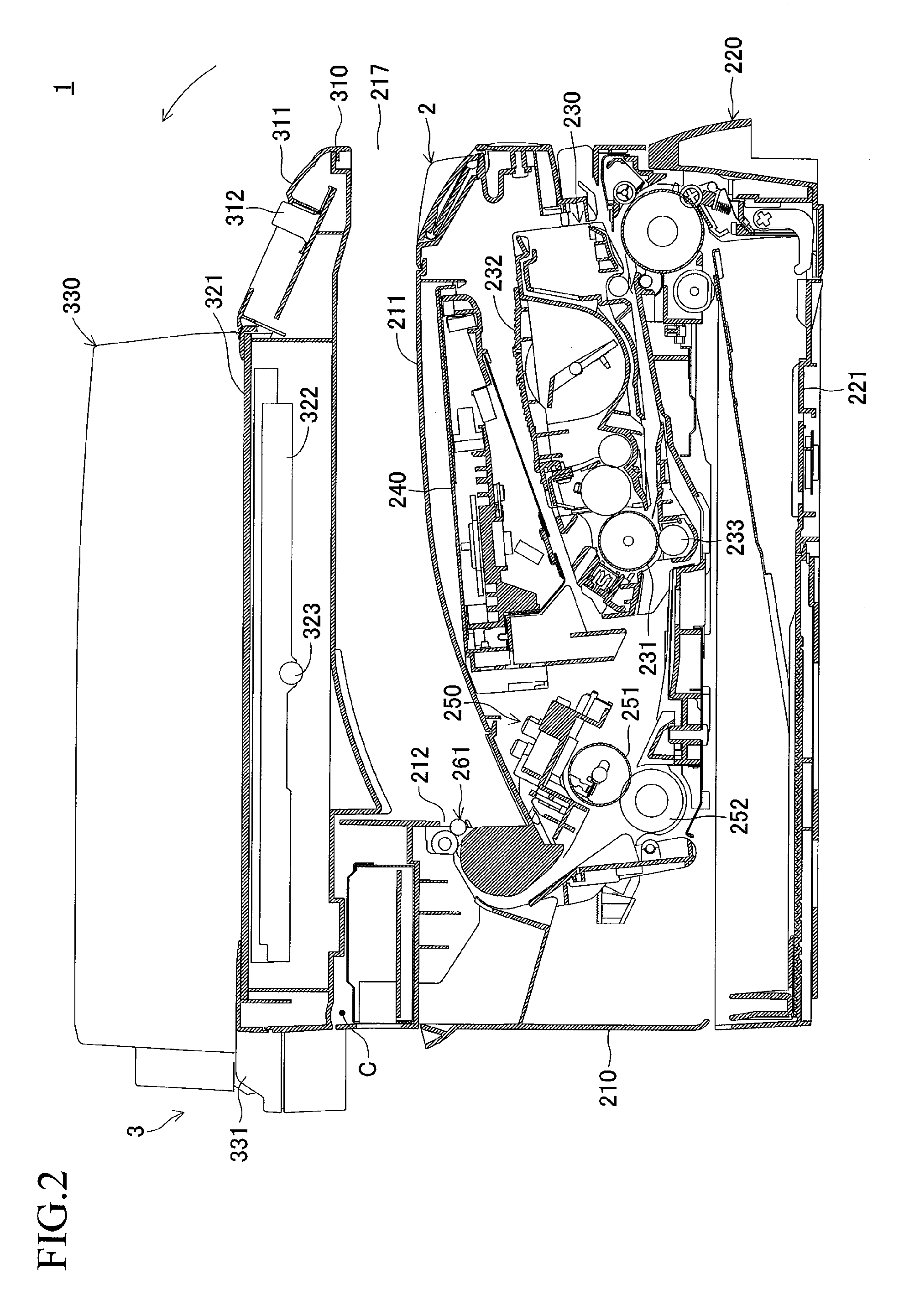
[0046]FIG. 2 is a sectional view of the printer section 2 and a lower portion of the image scanner section 3...


PUM


Abstract

An image scanner section is disposed above a printer section. The image scanner section is supported by the printer section in such a manner as to be pivotable about a pivotal axis. The printer section has a lower housing having a substantially rectangular shape as viewed from above. The image scanner section has an upper housing having a substantially rectangular shape as viewed from above. The upper housing and the lower housing are configured such that a second upper corner portion, which is a corner portion of the upper housing, projects beyond a second lower corner portion, which is a corner portion of the lower housing and is located just under the second upper corner portion.

Description

CROSS-REFERENCE TO RELATED APPLICATION[0001]This application claims priority from Japanese Patent Application No. 2006-290396, filed on Oct. 25, 2006, the entire subject matter of which is incorporated herein by reference.BACKGROUND OF THE INVENTION[0002]1. Field of the Invention[0003]The present invention relates to an image-forming apparatus.[0004]2. Description of the Related Art[0005]Conventionally, there is known an image-forming apparatus having an image-forming section, an image-reading section provided above the image-forming section, and a catch tray provided therebetween. The image-reading section has a function of reading a document image. The image-forming section has a function of forming an image on paper.[0006]Conventionally, there is also known the thus-configured image-forming apparatus in which the image-reading section is pivotable about a predetermined pivotal axis (disclosed in, for example, Japanese Patent Application Laid-Open (kokai) Nos. 10-301349, 2005-1653...

Claims


Application Information

Patent Timeline
IPC IPC(8): H04N1/04
CPCH04N1/00543G03G15/605H04N2201/0091H04N1/00554
Inventor ITO, SAKAEKUSAMA, TAKUROHATTORI, SATORU
Owner BROTHER KOGYO KK
Why Eureka
Try Eureka