Interlocking means and bag with interlocking means

a technology which is applied in the field of interlocking means and interlocking bags, can solve the problems of difficult to recognize by touch whether or not the interlocking is occurring, the handling characteristic of the bag may be reduced, and the opening/closing of the bag may be unintentionally left partly open, etc., to achieve the effect of easy opening/closing and easy opening/closing

Active Publication Date: 2018-07-05
C I TAKIRON CORP
View PDF9 Cites 1 Cited by
  • Summary
  • Abstract
  • Description
  • Claims
  • Application Information

AI Technical Summary

Benefits of technology

[0018]When the interlocking means of the present invention is used, full interlocking of male and female parts is easily recognized, opening / closing is easy, and leakage of even liquid or powdered contents stored in the bag can be inhibited.
[0019]In the bag with an interlocking means of the present invention, full interlocking of male and female parts is easily recognized, opening / closing is easy, and leakage of even liquid or powdered contents stored in the bag can be inhibited.

Problems solved by technology

However, it is difficult to recognize with fingers by touch whether or not interlocking is successful when the first and second interlocking parts are continuously interlocked by sliding the fingers.
For this reason, the opening of the bag may be unintentionally left partly opened.
However, as the interlocking strength increases, it is more difficult to interlock the first interlocking part and the second interlocking part, and a handling characteristic of the bag is reduced.
However, in a bag with an interlocking means for which the interlocking means is provided, when liquid or powdered contents are stored, there is a problem that the contents leak out through the cutout parts of the male interlocking part.

Method used


Image

  • Interlocking means and bag with interlocking means
  • Interlocking means and bag with interlocking means
  • Interlocking means and bag with interlocking means

Examples


Embodiment Construction

[Interlocking Means]

[0030]Hereinafter, an example of an interlocking means of the present invention will be described in detail.

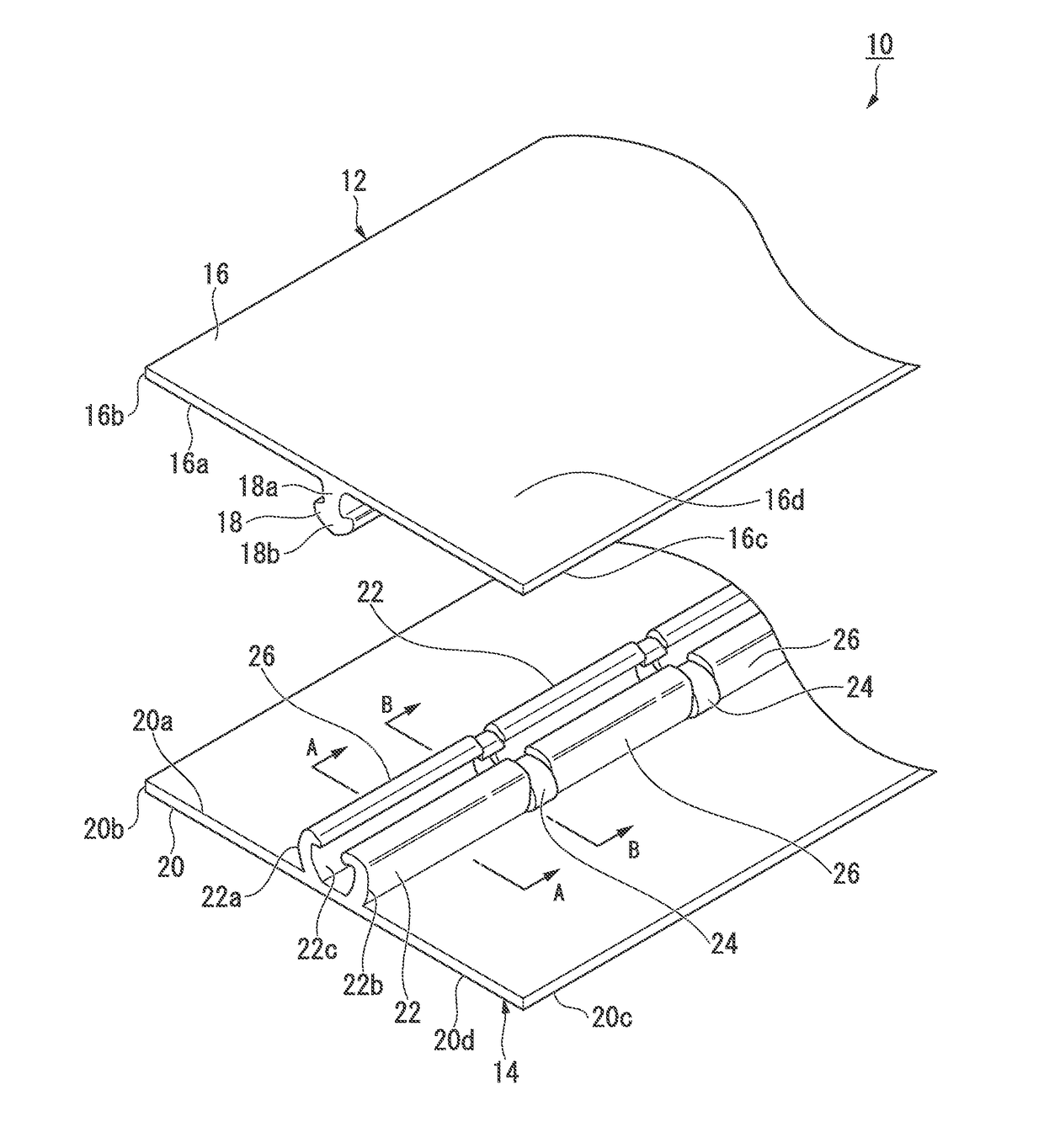
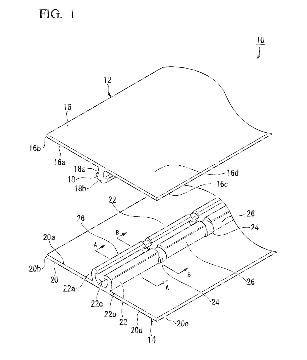
[0031]As shown in FIGS. 1 to 3, an interlocking means 10 includes a pair of band-shaped first and second interlocking members 12 and 14. The first interlocking member 12 includes a band-shaped first base 16 and a male interlocking part 18 provided in a longitudinal direction of the first base 16. The second interlocking member 14 includes a band-shaped second base 20 and a female interlocking part 22 provided in a longitudinal direction of the second base 20.

[0032]The interlocking means 10 of the present embodiment is attached to an inner surface of a bag main body such that a first lateral end 16b of the first base 16 and a first lateral end 20b of the second base 20 are at an opening side of the bag, and a second lateral end 16c of the first base 16 and a second lateral end 20c of the second base 20 are at a content side of the bag.

(First Interlocking Mem...


PUM

PropertyMeasurementUnit
lengthaaaaaaaaaa
heightsaaaaaaaaaa
interlocking strengthaaaaaaaaaa

Abstract

An interlocking means including a first interlocking member for which a male interlocking part is provided in a longitudinal direction of a band-shaped first base and a second interlocking member for which a female interlocking part is provided in a longitudinal direction of a band-shaped second base, and in which multiple sections whose heights are low are formed at the female interlocking part at intervals in a longitudinal direction of the female interlocking part, and the male interlocking part and the female interlocking part are interlocked in the low sections in the same manner as in the non-low sections; and a hag with an interlocking means in which the interlocking means is provided.

Description

TECHNICAL FIELD[0001]The present invention relates to an interlocking means and a bag with the interlocking means.[0002]Priority is claimed on Japanese Patent Application No. 2015-137689, filed on Jul. 9, 2015, the content of which is incorporated herein by reference.BACKGROUND ART[0003]A bag with an interlocking means attached to an inner surface around an opening of a bag main body to seal the opening such that it can be freely closed and reopened is widely used in various fields such as foods, drugs, sundries, and so on. In an example of the interlocking means, first and second interlocking parts, which are detachably interlocked with opposite surfaces of a pair of band-shaped bases, are provided in longitudinal directions of the bases.[0004]For example, an interlocking means in which both the first interlocking part and the second interlocking part have a plurality of male hook parts running parallel to each other, and heads of the mutual male hook parts are inserted between two...

Claims


Application Information

Patent Timeline
Patent Type & Authority Applications(United States)
IPC IPC(8): A44B19/16B65D33/25B29D5/00
CPCA44B19/16B65D33/255B65D33/2558B29D5/00B29L2031/7128B65D33/00B65D33/25B65D75/5805B65D33/2566B65D2203/12
Inventor OIKE, TAKAYUKIOBAYASHI, MASAYUKI
Owner C I TAKIRON CORP
Why Eureka
Try Eureka