Digital depth gauge

a digital depth gauge and depth measurement technology, applied in the field of measuring devices, can solve the problems of difficult to obtain an accurate measurement using such analog depth gauges, difficult to read scales under bright operating room lights, and inability to accurately measure bone depth

Active Publication Date: 2008-05-08
EDGE SURGICAL INC
View PDF27 Cites 58 Cited by
  • Summary
  • Abstract
  • Description
  • Claims
  • Application Information

AI Technical Summary

Benefits of technology

[0007]A digital depth gauge is provided for measuring a depth or length of a hole or bore in an object such as, for example a bone. In one embodiment the gauge includes: a proximally-oriented and generally stationary user interface portion including a display and at least one actuator; a reader shaft including a distal end and a proximal end connected to the user interface portion; a probe that extends from the distal end of the reader shaft and which includes a tip configured to locate a distal surface of the hole; a sleeve member including a distal end configured to abut a proximal surface of the hole, the sleeve member being coupled with the reader shaft for relative translational and rotational movement; and a sensor interposed between the reader shaft and the sleeve member for measuring relative translational movement between the reader shaft and the sleeve member. In some embodiments, the gauge may include a means for aligning elements of the sensor.

Problems solved by technology

Because drilling does not provide an exact measurement of the depth of the bone, surgeons sometimes use a conventional analog depth gauge to measure the depth of the hole.
In some instances, surgeons find it difficult to obtain an accurate measurement using such analog depth gauges.
In one situation, the scale may be difficult to read under bright operating room lights.
While such digital surgical depth instruments are useful for measuring depths of holes in bones which are in relatively shallow surgical fields, such instruments may be difficult to use when attempting to address bone measurement issues of the spine, hip, pelvis or other deep areas.
Thus, when the surgeon must work within a body space that is deep and sufficiently constraining, it can be appreciated that such digital surgical depth instruments may be awkward to position and obtain readings from because the display may be oriented inside the deep surgical field, distal from the surgeon.

Method used


Image

  • Digital depth gauge
  • Digital depth gauge
  • Digital depth gauge

Examples


Embodiment Construction

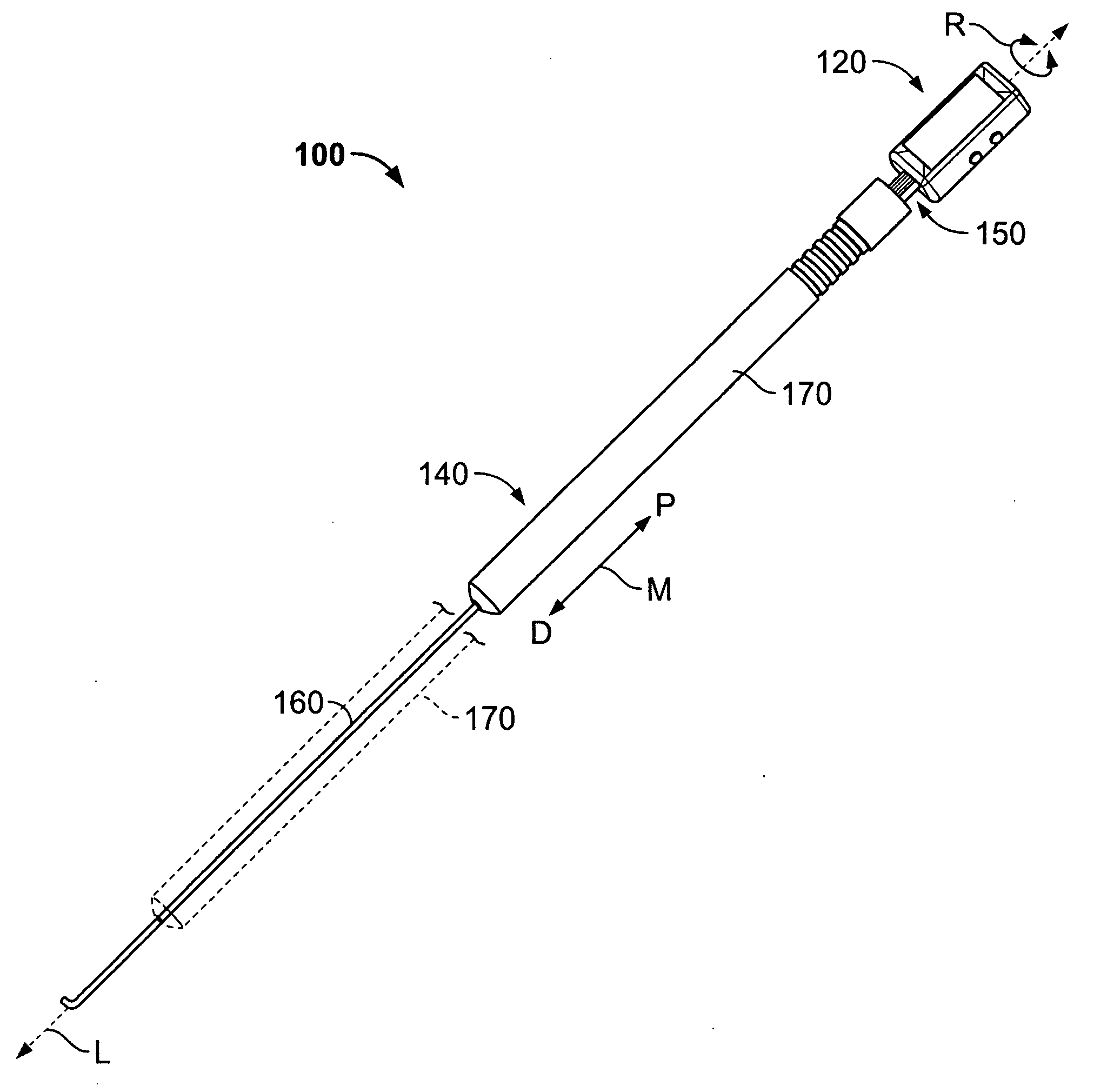
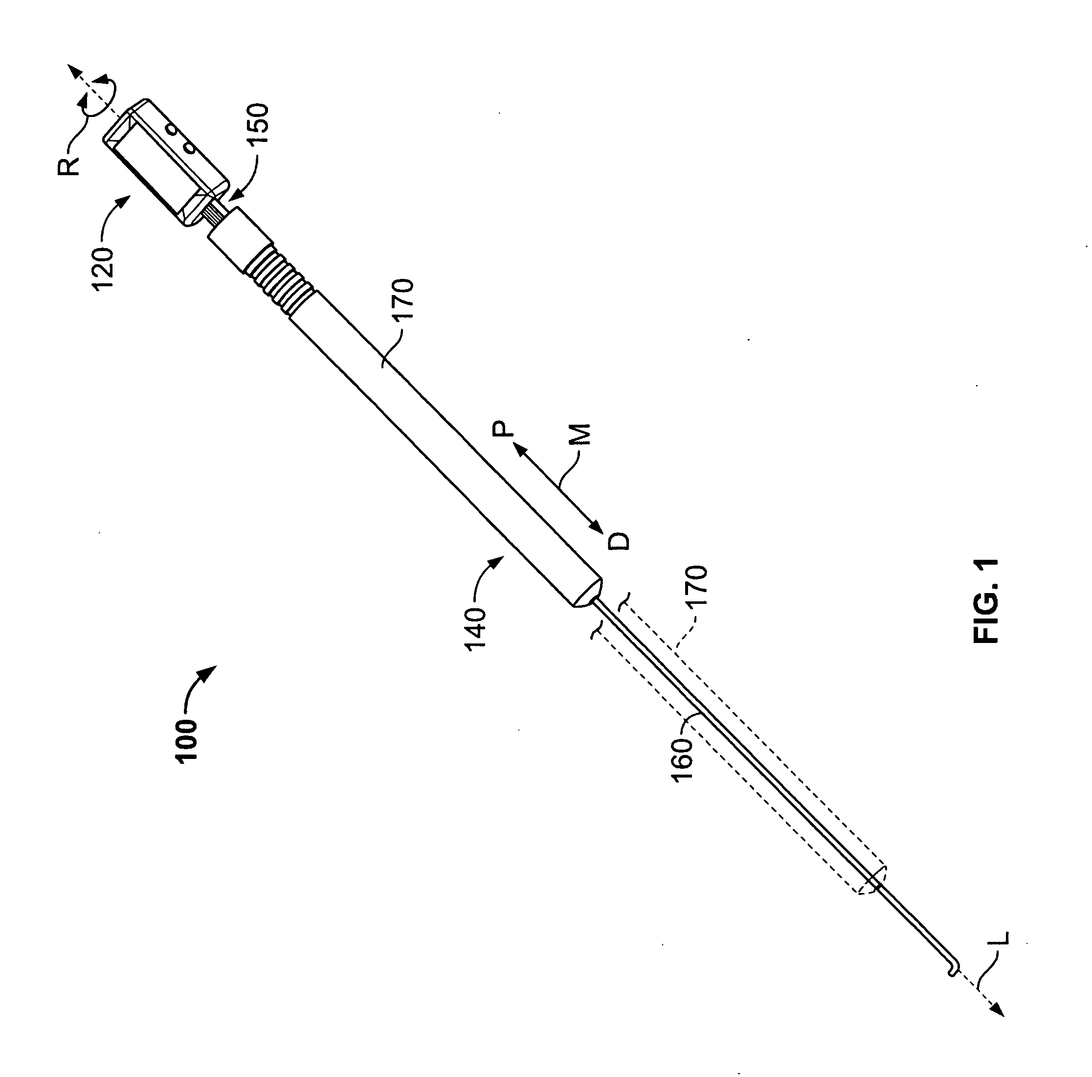
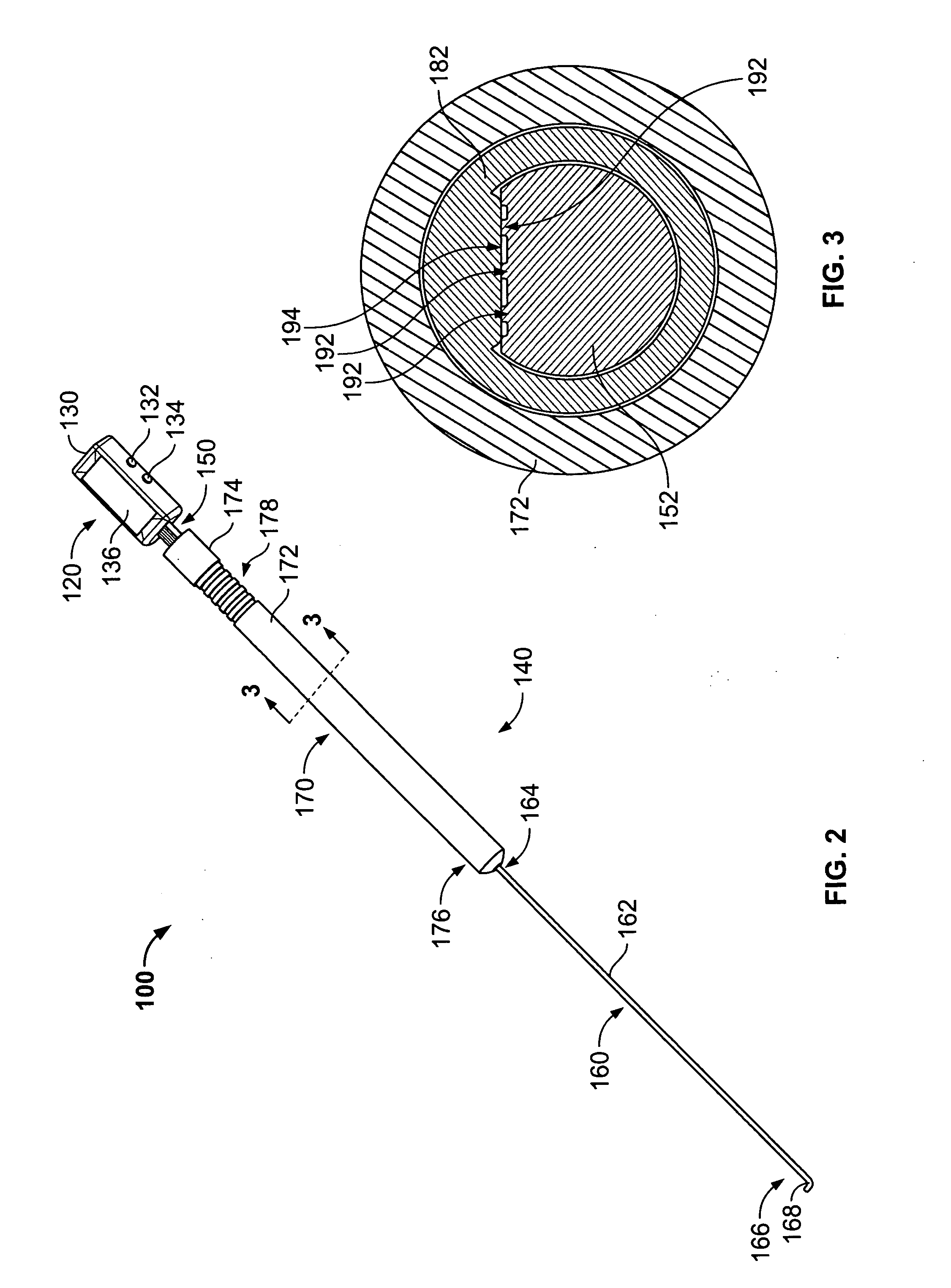
[0017]Referring now to the Figures an embodiment of a digital spinal depth gauge is provided. The embodiment may be employed for various applications where it is desired to determine an accurate length or depth of a hole or bore in an object. One such application is, for example, a medical procedure where a surgeon needs to drill a hole through one or more bones, or pieces of bone, and select a screw, pin or other fastener known in the art for insertion through the hole such that the bone or bones may be connected, fused or otherwise repaired. In one embodiment, because the user interface portion is proximally-oriented and generally stationary during the process of using the gauge to take a measurement, use of the gauge is particularly advantageous for measuring depths of bones in relatively deep surgical fields, such as when attempting to address bone measurement issues of the spine, hip, pelvis or other areas. Although one embodiment of the gauge may be advantageous for the forego...


PUM


Abstract

A digital depth gauge is provided for measuring a depth of a hole in an object. In one embodiment the gauge includes: a user interface with a display and at least one actuator; a reader shaft with a distal end and a proximal end connected to the user interface; a probe that extends from the distal end of the reader shaft and which includes a tip configured to locate a distal surface of the hole; a sleeve member with a distal end configured to abut a proximal surface of the hole, the sleeve member being coupled with the reader shaft for relative translational and rotational movement; and a sensor interposed between the reader shaft and the sleeve member for measuring relative translational movement between the reader shaft and the sleeve member. In some embodiments, the gauge may include a means for aligning elements of the sensor.

Description

FIELD OF THE INVENTION[0001]This invention relates generally to measuring apparatuses and more particularly to a digital measuring device that is configured to measure a length or depth of a hole or bore in an object (e.g., a bone).BACKGROUND OF THE INVENTION[0002]Many surgical procedures require surgeons to secure a device to the bone of a patient. In some procedures, the surgeon spans and secures one or more bones, or pieces of bone, using a bone plate and screws or other fasteners. In other procedures, the surgeon uses a screw or other fastener without another device, for example, to secure a transplanted tendon. In many procedures, the surgeon drills a hole in the bone prior to securing the fastener to the bone. With a hole in place, the surgeon can more easily select a fastener of the appropriate length. Selection of an appropriate length fastener may be important in some instances to avoid complications because, as can be appreciated, if the fastener is too long, the fastener ...

Claims


Application Information

Patent Timeline
Patent Type & Authority Applications(United States)
IPC IPC(8): G01B3/28
CPCG01B3/28A61B5/103A61B5/107G01B5/18
Inventor KIM, JOHN Y. S.KAGANOVSKY, ARTUR
Owner EDGE SURGICAL INC
Why Eureka
Try Eureka