Radio base station, relay station, and relay method

Inactive Publication Date: 2008-05-08
FUJITSU LTD
View PDF8 Cites 82 Cited by
  • Summary
  • Abstract
  • Description
  • Claims
  • Application Information

AI Technical Summary

Benefits of technology

[0031] According to one embodiment of the present invention, data can be resent in an efficient manner even

Problems solved by technology

However, even within the service area in which the radio base station can carry out radio communication, high speed communication may not be available in a place close to the area boundary, since the radio environment may not be satisfactory.
Further, even within the area, radio signal propagation may be obstructed by a cause such as building shading.
Thus, an area (so-called dead zone) in which satisfactory radio c

Method used


Image

  • Radio base station, relay station, and relay method
  • Radio base station, relay station, and relay method
  • Radio base station, relay station, and relay method

Examples


first embodiment

[a] Description of First Embodiment

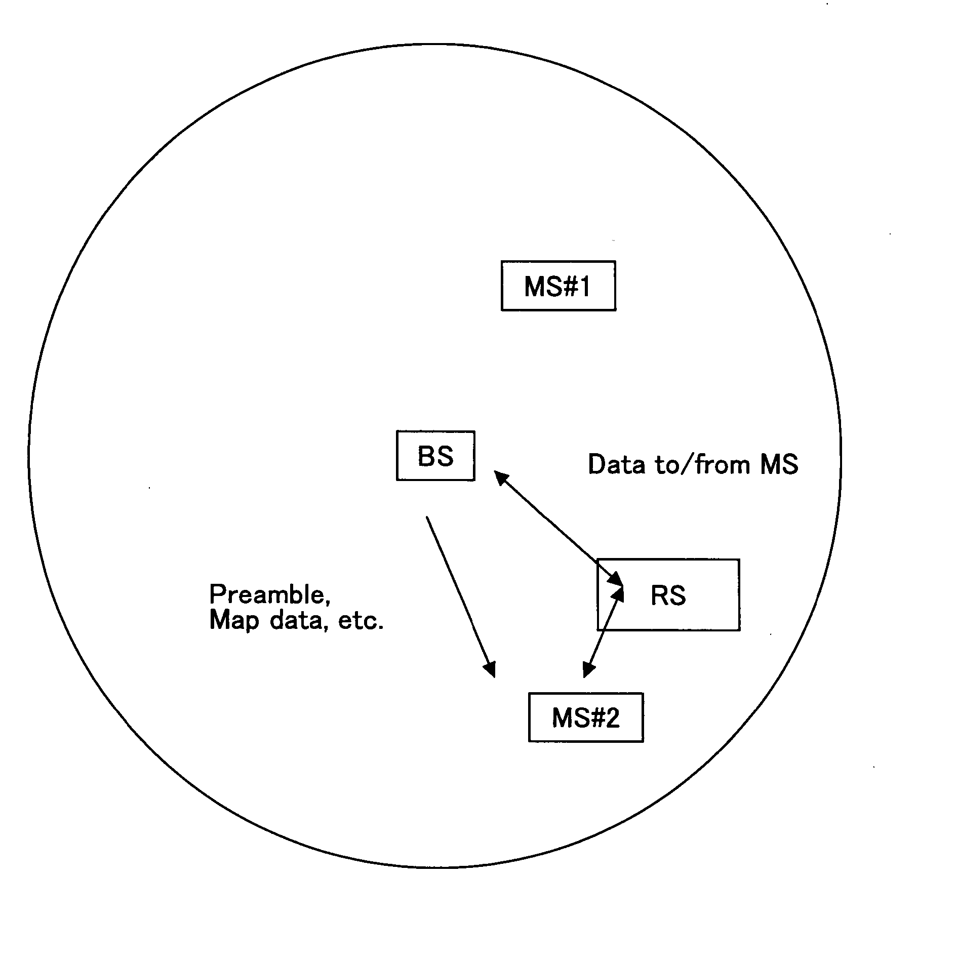
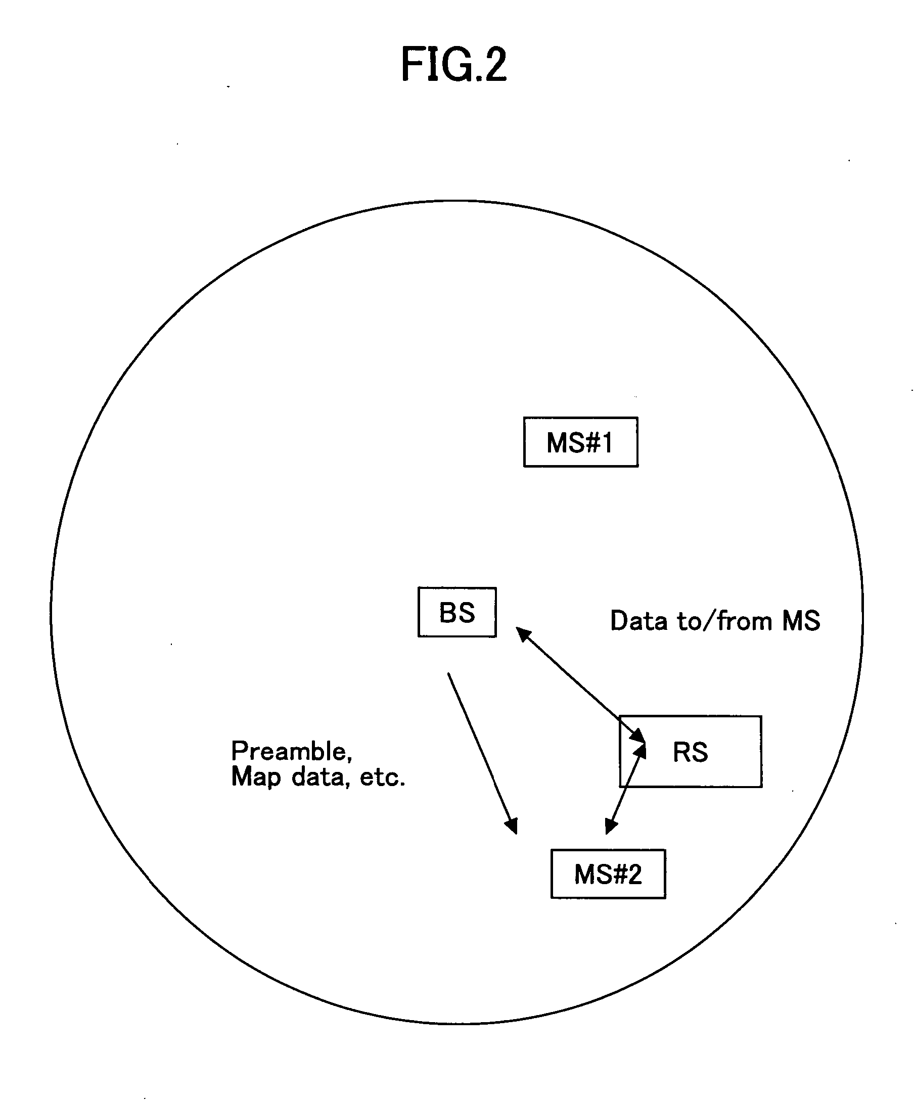
[0057]FIG. 3 is a sequence diagram of a process performed by a radio communication system according to a first embodiment of the present invention. In the first embodiment, a relay station is additionally installed in a radio communication system defined by IEEE 802.16 including a radio base station and a radio terminal performing radio communication with each other. As a matter of course, this process sequence is applicable to any other radio communication system provided with a relay apparatus.

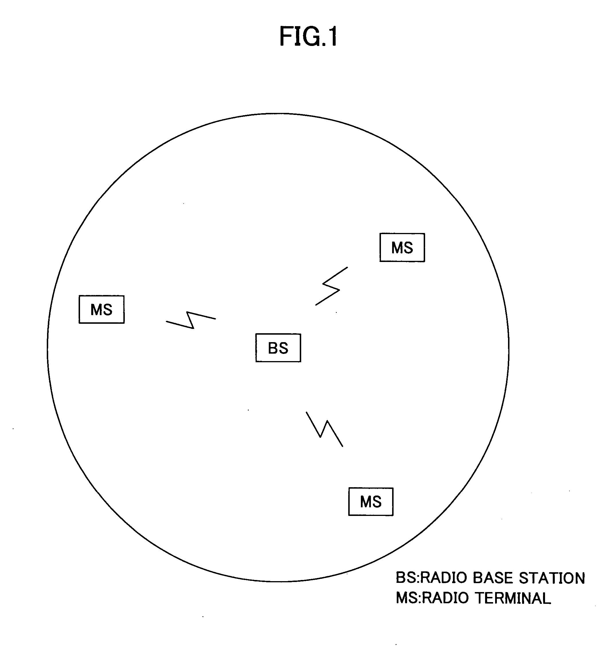
[0058] In FIG. 3, BS (Base Station) indicates a radio base station, which is one of a plurality of radio base stations arranged in a distributed manner in an area providing a radio communication service based on this radio communication system. There are other BSs forming radio areas adjacent to the radio area formed by this BS, although not illustrated herein.

[0059] In this radio communication system, transmission / reception channels (uplink and downlink ...

second embodiment

[b] Description of Second Embodiment

[0108] In the first embodiment, when data is transmitted from a transmitting side apparatus (e.g., BS) via the RS to a receiving side apparatus (e.g., MS), and a resending operation is to be performed, the data is resent once again from the transmitting side apparatus (e.g., BS) via the RS to the receiving side apparatus (e.g., MS).

[0109] In the second embodiment, the RS is used in an effective manner so that radio transmission is performed more efficiently.

[0110] For example, in a case where the RS receives data from the MS (BS) and relays the received data to the BS (MS), and then the BS (MS) makes a resending request, the data can be resent originating from the RS. The data is preferably resent originating from the RS only when the RS can acquire properly received data from the transmitting side, apparatus. If the RS cannot decode properly received data, and the data is resent originating from the RS, it is unlikely that data will be properly...

third embodiment

[c] Description of Third Embodiment

[0202] Next, descriptions are given of downlink data transmission.

[0203]“Downlink data transmission (part 1)”

[0204]FIGS. 15 and 16 are sequence diagrams of downlink data transmission (part 1).

[0205]FIGS. 17 and 18 illustrate operation flows (part 1) of the RS and the BS, respectively.

[0206] In this example, HARQ is employed for controlling the resending operation, and data that is the target of HARQ control is referred to as HARQ data. In a case where ARQ control is employed, the received data does not need to be saved for the purpose of combining data.

[0207] Referring to FIG. 15, the BS acquires, from the packet buffer unit 12, a preamble, MAP data, and data corresponding to a region defined by the MAP data, which are generated by the MAP information generating unit 9, forms a subframe at the PDU generating unit 13, and transmits the subframe from the transmitting unit 16 via the antenna 1.

[0208] The RS and the MS receive the MAP data from th...


PUM


Abstract

A disclosed relay station is provided between a radio base station and a radio terminal for relaying a radio signal. The relay station includes a receiving unit configured to receive data transmitted from the radio base station or the radio terminal; a storage unit configured to hold the data; and a transmitting unit configured to relay the data to the radio terminal or the radio base station, and resend the data originating from the relay station in the event that the data need to be resent.

Description

BACKGROUND OF THE INVENTION [0001] 1. Field of the Invention [0002] The present invention relates to a radio base station, a relay station, and a relay method using radio communication. The present invention is especially advantageous when it is applied to a case where a radio communication system prescribed by IEEE 802.16 is used as a base system and thereto a relay station is added. [0003] 2. Description of the Related Art [0004] A radio communication system carrying out communication with the use of a radio channel, i.e., WCDMA, CDMA2000 or such, as a typical example, currently spreads worldwide. In such a radio communication system, a plurality of radio base stations are set for a service area, and each radio terminal carries out communication with another communication apparatus (i.e., another communication terminal) with the use of any of the radio base stations. At this time, an overlapping area is provided with an adjacent service area in which an adjacent base station can c...

Claims


Application Information

Patent Timeline
IPC IPC(8): H04B7/14H04B7/15H04L12/70H04L12/801H04L12/911H04W16/26H04W24/10H04W28/00H04W28/04H04W28/14H04W92/20
CPCH04B7/15542H04L1/1812H04W84/047H04W16/26H04W28/14H04L2001/0097H04B7/14H04L1/18H04W88/08
Inventor SUGA, JUNICHI
Owner FUJITSU LTD
Why Eureka
Try Eureka