Acceleration sensor

Active Publication Date: 2008-05-15
MITSUBISHI ELECTRIC CORP
View PDF8 Cites 43 Cited by
  • Summary
  • Abstract
  • Description
  • Claims
  • Application Information

AI Technical Summary

Benefits of technology

[0023]Therefore, by providing the detection electrodes in such a manner that the sensitivity thereof can be increased only when the first and second detection frames are rotationally displaced in the directions op

Problems solved by technology

Therefore, there is a problem that the det

Method used


Image

  • Acceleration sensor
  • Acceleration sensor
  • Acceleration sensor

Examples


embodiment 1

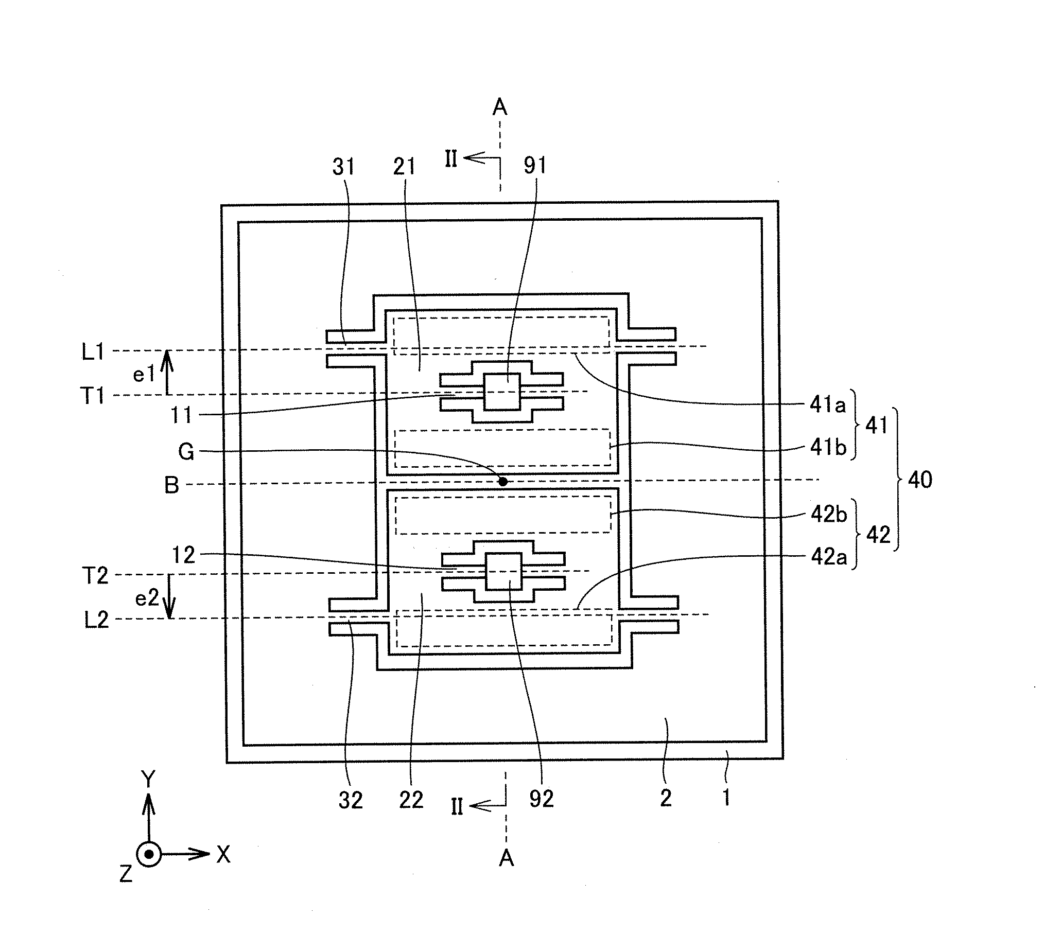
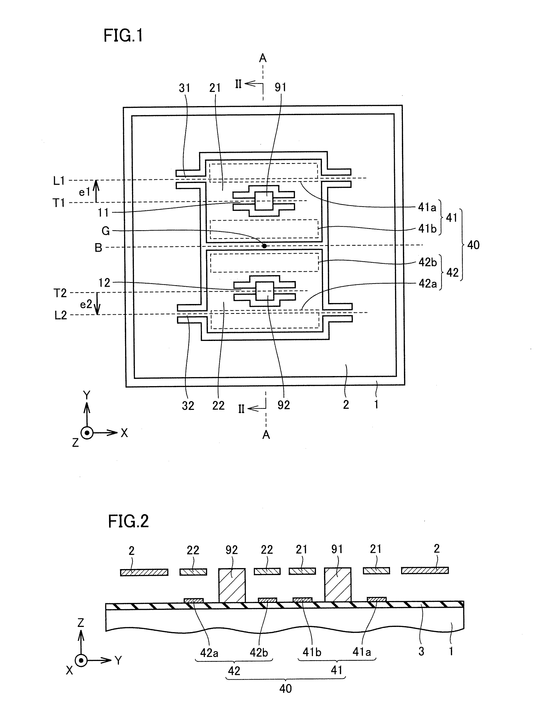
[0052]First, a main constitution of an acceleration sensor according to the present embodiment is explained.

[0053]Referring to FIGS. 1 and 2, the coordinate axes of the X axis, the Y axis and the Z axis are introduced for convenience of explanation. In FIG. 1, the X axis is an axis in which the right direction along the lateral direction is the positive direction, the Y axis is an axis in which the upper direction along the longitudinal direction is the positive direction, and the Z axis is an axis which is vertical to the paper surface and in which the upper direction is the positive direction. Note that the direction of the Z axis coincides with the acceleration direction to be measured by the acceleration sensor according to the present embodiment.

[0054]The acceleration sensor according to the present embodiment mainly includes a substrate 1, first and second torsion beams 11 and 12, first and second detection frames 21 and 22, a plurality of detection electrodes 40, first and se...

embodiment 2

[0102]Referring to FIGS. 14 and 15, in an acceleration sensor according to the present embodiment, an actuation electrode 5 is formed on substrate 1 so as to face inertia mass body 2.

[0103]Note that since the constitution other than this part is the same as the above described constitution of Embodiment 1, the same components are denoted by the same reference numerals and characters, and the explanation of the components is omitted.

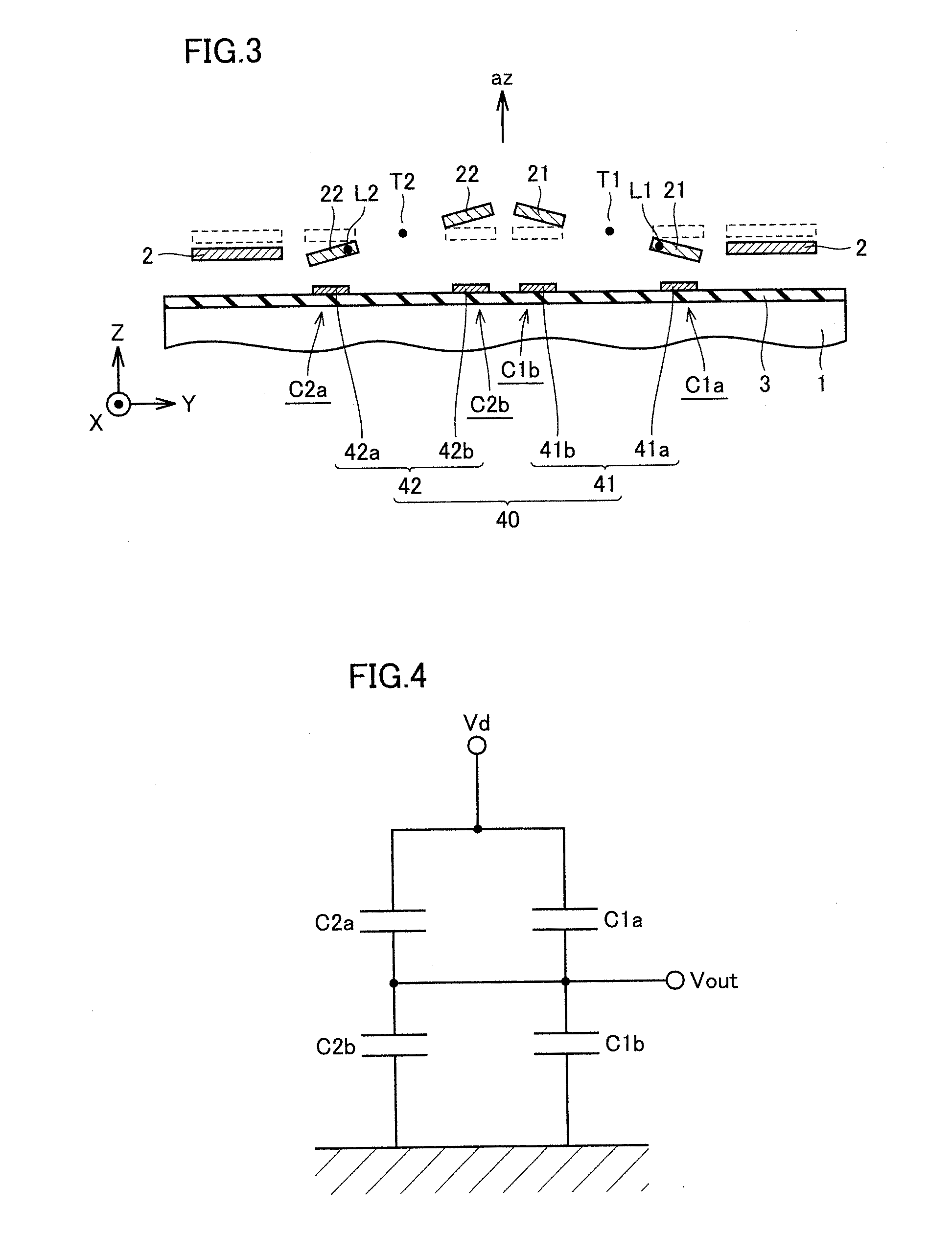
[0104]According to the present embodiment, as shown by the arrow shown in FIG. 15, electrostatic force pulling inertia mass body 2 toward substrate 1 can be generated by applying a voltage between actuation electrode 5 and inertia mass body 2. That is, inertia mass body 2 can be electrostatically driven in the film thickness direction of substrate 1. This electrostatic drive makes it possible to generate the displacement of inertia mass body 2 equivalent to the displacement in the case where acceleration az in the film thickness direction of substrate 1 i...

embodiment 3

[0105]Referring to FIG. 16, an acceleration sensor according to the present embodiment includes anchors 90 on substrate 1 and supporting beams 4.

[0106]One end part of supporting beam 4 is supported above substrate 1 by anchor90. Further, the other end part of supporting beam 4 supports inertia mass body 2.

[0107]Supporting beam 4 has a first supporting beam 4X and a second supporting beam 4Y. First supporting beam 4X has a shape which can be easily elastically deformed in the Z axis direction and hardly elastically deformed in the X axis direction. Second supporting beam 4Y has a shape which can be easily elastically deformed in the Z axis direction and hardly elastically deformed in the Y axis direction. For this reason, supporting beam 4 as a whole has a constitution which can be easily elastically deformed in the Z axis direction and hardly elastically deformed in the XY in-plane direction.

[0108]Note that since the constitution other than this part is the same as the above describ...


PUM


Abstract

First and second detection frames are supported by a substrate to be rotatable about first and second torsion axes. A first link beam is connected to the first detection frame on an axis located at a position moved from a position of the first torsion axis in a first direction crossing the first torsion axis and directed to one end side of the first detection frame. A second link beam is connected to the second detection frame on an axis located at a position shifted from a position of the second torsion axis in a second direction opposite to the first direction. An inertia mass body is displaceable in a thickness direction of the substrate by being linked with the first and second detection frames by the first and second link beams, respectively. This constitution makes it possible to obtain a highly precise acceleration sensor hardly influenced by disturbances.

Description

[0001]The value of formula (2) is decreased, when inertia mass body 2 is sunk as shown in FIG. 3. Further, when the acceleration in the direction opposite to the direction of acceleration az (FIG. 3) is applied to the acceleration sensor, inertia mass body 2 is displaced in the upward direction along the thickness direction of substrate 1, so as to increase the value of formula (2). As a result, the displacement of inertia mass body 2 in the thickness direction of substrate 1 is detected by measuring output potential Vout, so that acceleration az in the Z axis direction can be detected from this detection.[0002]Next, examples when movements other than the acceleration in the Z direction are applied to the acceleration sensor according to the present embodiment are explained.[0003]Referring to FIG. 5, when inertia mass body 2 receives negative angular acceleration ac in the X axis direction around its center of gravity G, inertia mass body 2 is inclined by being rotationally displace...

Claims


Application Information

Patent Timeline
IPC IPC(8): G01P15/125
CPCG01P15/125
Inventor KONNO, NOBUAKIHIRATA, YOSHIAKI
Owner MITSUBISHI ELECTRIC CORP
Why Eureka
Try Eureka