Stabilizer control device

a control device and stabilizer technology, applied in the direction of vehicle springs, resilient suspensions, interconnection systems, etc., can solve the problems of large load added to the clutch mechanism, unavoidable actuator size as a whole, and deterioration of ride quality, so as to reduce the relative rotational torque

Inactive Publication Date: 2008-05-15
AISIN SEIKI KK
View PDF5 Cites 11 Cited by
  • Summary
  • Abstract
  • Description
  • Claims
  • Application Information

AI Technical Summary

Benefits of technology

[0010]According to an aspect of the present invention, a stabilizer control device includes a first stabilizer bar connected to one of right and left wheels, a second stabilizer bar connected to the other one of the right and left wheels, a housing fixed to an end portion of the second stabilizer bar so as to arrange an end portion of the first stabilizer bar adjacent to the end portion of the second stabilizer bar and to accommodate the end portion of the first stabilizer bar, a rotational torque reducing mechanism having an input portion fixed to the first stabilizer bar and the housing and reducing a relative rotational torque between the housing and the first stabilizer bar so as to output the relative rotational torque, a hollow member accommodating therein the first stabilizer bar so as to rotatably support the first stabilizer bar within the housing and fixed with an output portion of the rotational torque reducing mechanism so as to rotatably support the output portion within the housing; and a clutch mechanism arranged between the hollow member and the housing for engaging the hollow member and the housing with each other and disengaging from each other, wherein the first and second stabilizer bars are connected and disconnected.

Problems solved by technology

In the roll stabilizer according to the Patent Document 1, it is unavoidable for the actuator to have a large size as a whole.
For example, when the vehicle is running straight ahead on extremely unsteady roads such as rough or bumpy roads even with the electric motor described in the Patent Document 1 switched off for the purpose of stopping the roll stabilizing function, ride quality may be deteriorated by sudden inputs added to the speed reducing gear mechanism from the stabilizer.
However, for example, in the stabilizer control device according to the Patent Document 4, when the clutch mechanism is configured to be arranged between the pair of stabilizer bars in such a way to be directly connected to the stabilizer bars, a large load is added to the clutch mechanism.
Especially, since an end portion of the stabilizer bar must be fixed to a suspension member during installation, the large-size actuator has a disadvantage of installation flexibility due to limitations of space.

Method used


Image

  • Stabilizer control device
  • Stabilizer control device
  • Stabilizer control device

Examples


first embodiment

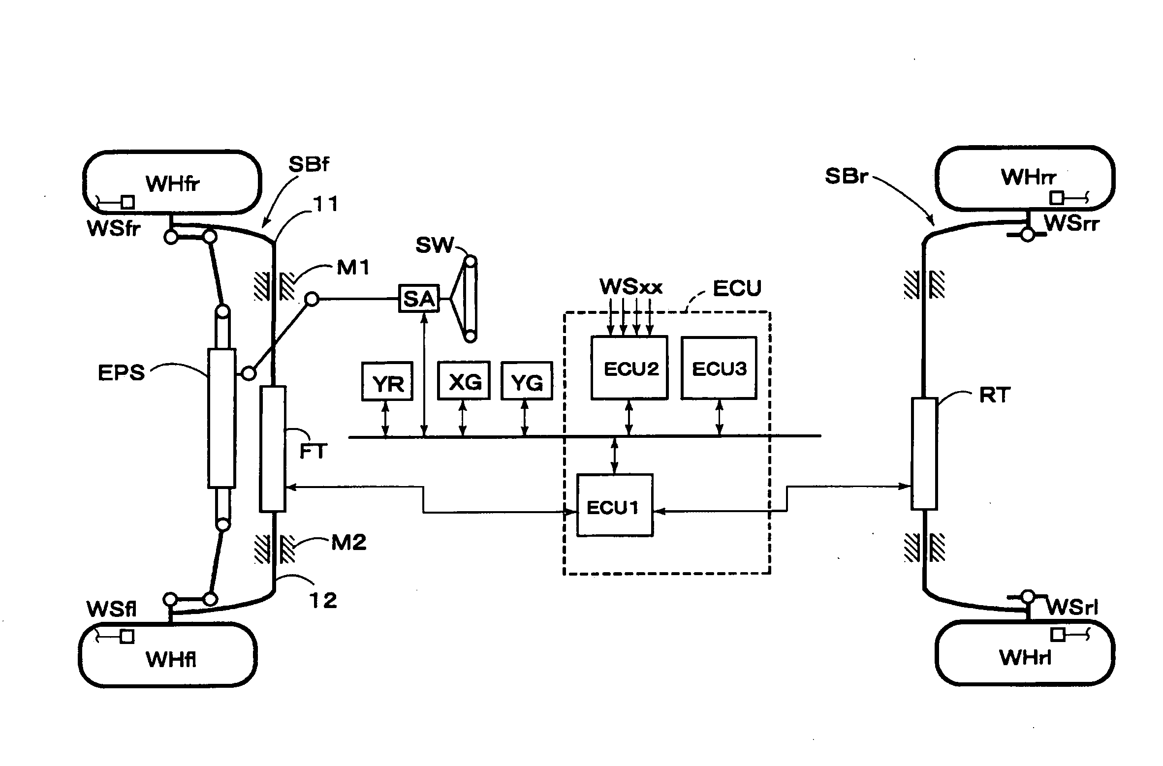
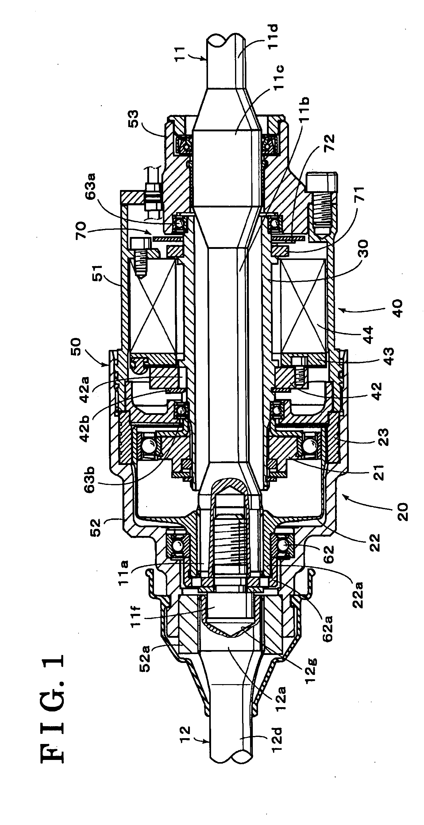
[0018]FIG. 1 illustrates a stabilizer control device for a vehicle according to a FIG. 5 is a configuration diagram illustrating an overview of the vehicle equipped with the stabilizer control device. Firstly, as illustrated in FIG. 5, the stabilizer control device for the vehicle includes a stabilizer SBf for front wheels and a stabilizer SBr for rear wheels, which stabilizers SBf and SBr serve as torsion springs when a rolling motion is inputted to a vehicle body (not shown). The stabilizer SBf for the front wheels are configured in a manner that a stabilizer actuator FT connects and disconnects a transmitting path of a torsion force for controlling the vehicle body roll angle corresponding to the rolling motion of the vehicle. Likewise, the stabilizer SBr for the rear wheels are configured in a manner that a stabiliser actuator RT connects and disconnects a transmitting path of a torsion force for controlling the vehicle body roll angle corresponding to the rolling motion of the...

third embodiment

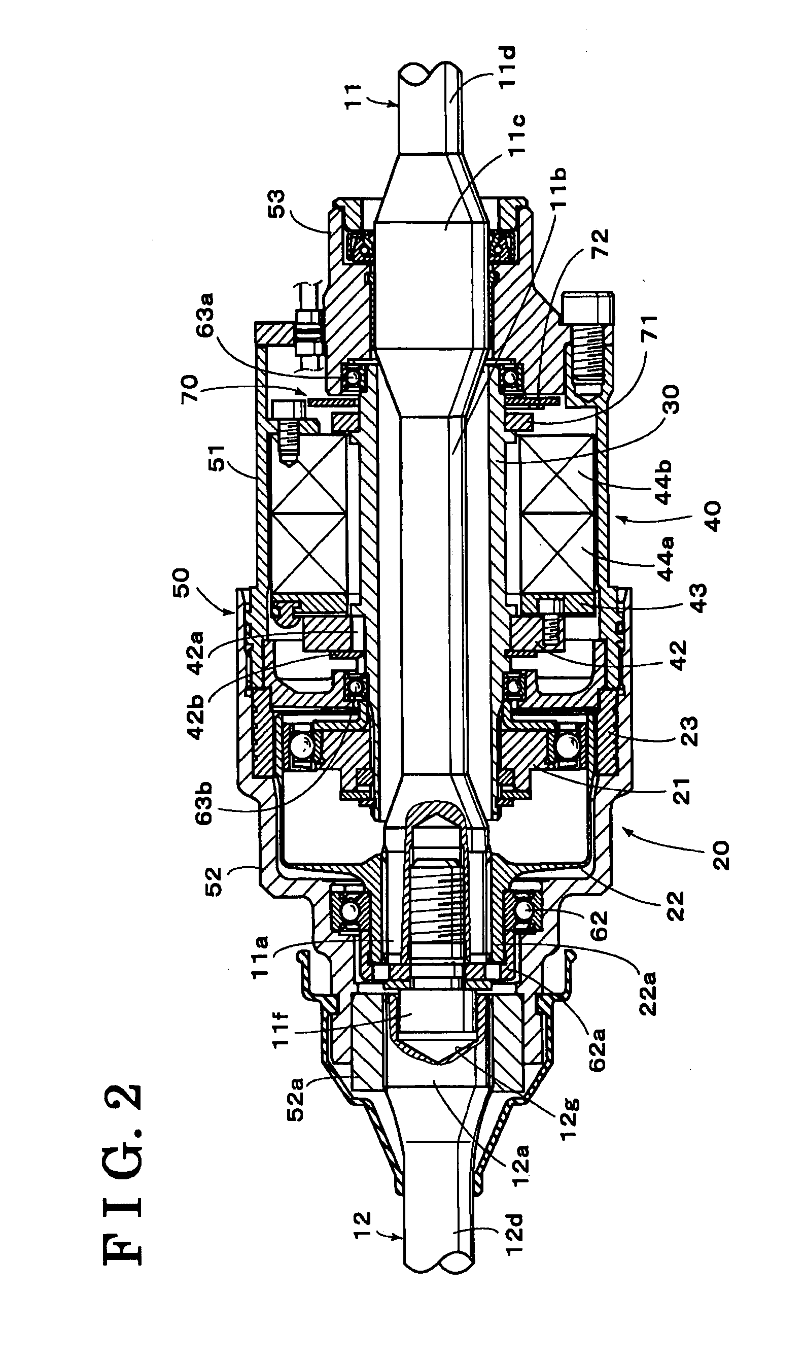
[0035]In the third embodiment illustrated in FIG. 3, when the solenoids 441 and 442 in the clutch mechanism 400 are not excited, the rotating members 421 is disengaged from the contact member 431 and the rotating member 422 is disengaged from the contact member 432, so that the hollow member 30 and the housing 50 are disengaged and separated from each other. Accordingly, the first and second stabilizer bars 11 and 12 are separated from each other, thereby freely rotating respectively. On the contrary, when the solenoid 441 or the solenoid 442 is excited by the stabilizer control unit ECU1, the rotating member 421 is frictionally engaged with the contact member 431 or the rotating member 422 is frictionally engaged with the contact member 432, so that the hollow member 30 and the housing 50 are connected to each other. Accordingly, the first and second stabilizer bars 11 and 12 are connected to each other via the hollow member 30, the clutch mechanism 400, and the housing 50. Hereby,...


PUM


Abstract

A stabilizer control device for a vehicle includes a first and second stabilizer bars, a housing fixed to an end portion of the second stabilizer bar so as to arrange an end portion of the first stabilizer bar adjacent to the end portion of the second stabilizer bar, a rotational torque reducing mechanism having an input portion fixed to the first stabilizer bar and the housing and reducing a relative rotational torque between the housing and the first stabilizer bar and outputting, a hollow member including the first stabilizer bar so as to rotatably support the first stabilizer bar within the housing and fixed with an output portion of the rotational torque reducing mechanism so as to rotatably support the output portion within the housing, and a clutch mechanism arranged between the hollow member and the housing for engaging and disengaging therebetween.

Description

CROSS REFERENCE TO RELATED APPLICATIONS[0001]This application is based on and claims priority under 35 U.S.C. § 119 to Japanese Patent Application 2006-304402, filed on Nov. 9, 2006, the entire content of which is incorporated herein by reference.FIELD OF THE INVENTION[0002]The present invention relates to a stabilizer control device for a vehicle. More specially, the present invention pertains to a stabilizer control device for connecting and disconnecting a pair of stabilizer bars arranged between right and left wheels.BACKGROUND[0003]A stabilizer control device for a vehicle is generally configured to reduce or control rolling movement of a vehicle body by externally applying an appropriate roll moment to the vehicle body by use of the actuation of stabilizer bars while the vehicle is turning. In order to implement such roll stabilizing function, for example, a roll stabilizer for a vehicle described in JP 2002-518245A (hereinafter referred to as Patent Document 1) includes halve...

Claims


Application Information

Patent Timeline
Patent Type & Authority Applications(United States)
IPC IPC(8): B60G17/00
CPCB60G17/0162B60G21/0556B60G2202/42B60G2204/4191B60G2204/8302B60G2204/419B60G2204/82
Inventor TANEDA, AKIYAOGUE, KENSAKAI, TOSHIYUKI
Owner AISIN SEIKI KK
Why Eureka
Try Eureka