Bearing module for a vacuum pump

a technology of bearing module and vacuum pump, which is applied in the direction of bearings, shafts, engine lubrication, etc., can solve the problems of affecting the service life of the pump, so as to achieve satisfactory circulation of lubricant and multi-layered capability

Inactive Publication Date: 2008-05-15
PFEIFFER VACUUM GMBH
View PDF4 Cites 27 Cited by
  • Summary
  • Abstract
  • Description
  • Claims
  • Application Information

AI Technical Summary

Benefits of technology

[0008]This and other objects of the present invention, which will become apparent hereinafter, are achieved by providing, in the bearing module of the type discussed above, radial delivery means on a side of the rolling bearing opposite a side of the bearing at which the delivery structure or element is located, for returning the lubricant to the reservoir. The delivery means operates under the action of capillary forces. The radial delivery means permits to obtain a lubricant circulation loop that is advantageously independent of the gravity forces. This permits to use the pump in different positions, without the lubrication of the bearing being adversely affected. Thereby, there is provided a simple construction with which advantages of a multi-layered capability are achieved. Because of the use of the capillary forces, the invention insures a satisfactory circulation of the lubricant at small amounts of the lubricant.

Problems solved by technology

The lubricant generally undergoes changes and becomes contaminated with impurities.
Despite lubrication, the rolling bearings are still subjected to wear because of friction.
One of the problems of the solution according to the state of the art consists in that the preload should be precisely adjusted after replacement of the bearing in the pump in which the shaft support arrangement is used.
This makes servicing of the pumps more difficult.
Moreover, the gravity force may be insufficient for returning the lubricant into the reservoir, as the gravity field of the earth depends on the orientation of the pump in space.
To insure a reliable circulation of the lubricant, expensive constructions are used in the state of the art.

Method used


Image

  • Bearing module for a vacuum pump
  • Bearing module for a vacuum pump
  • Bearing module for a vacuum pump

Examples


first embodiment

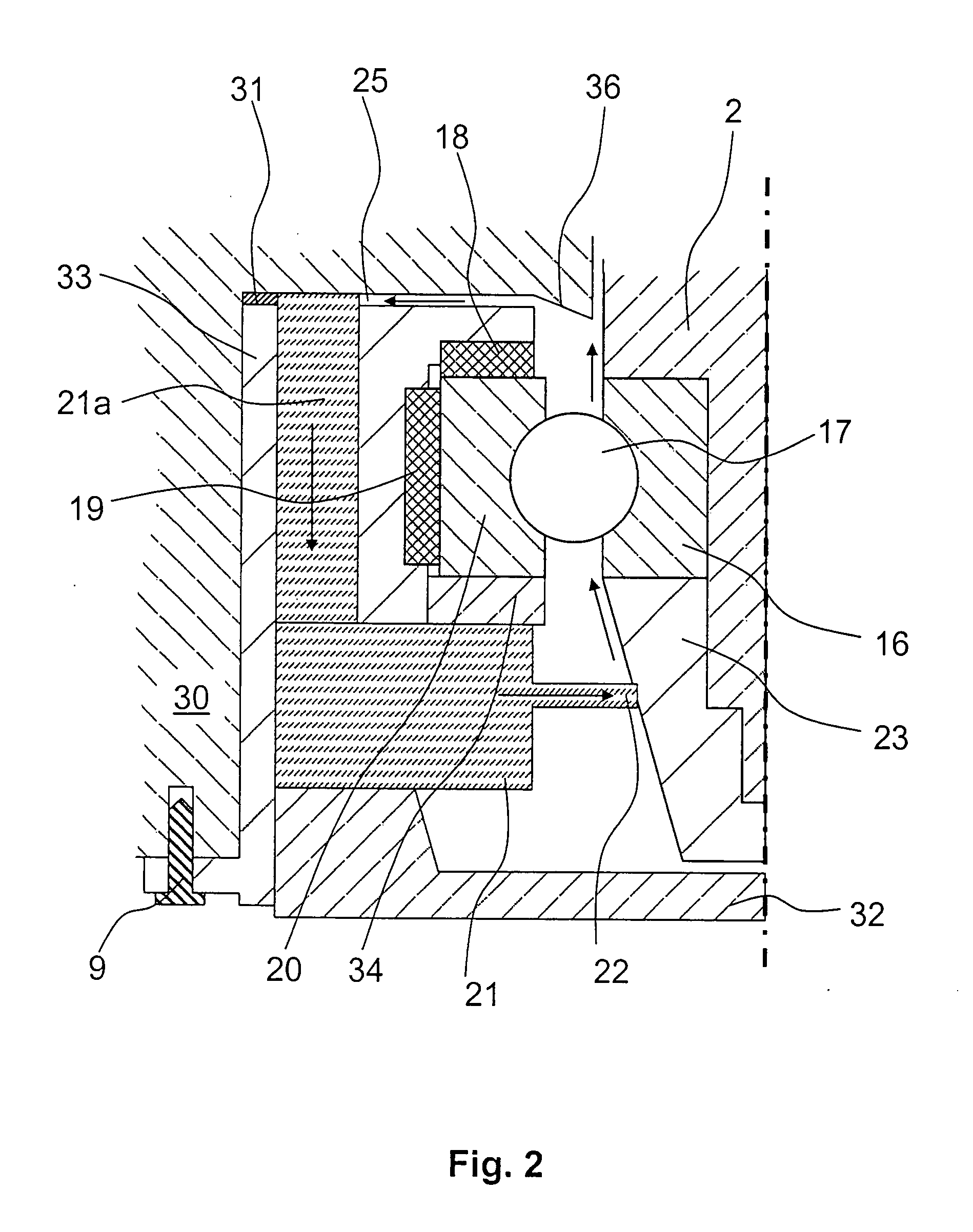
[0023]the bearing module according to the present invention is shown in FIG. 2. The bearing module 33 is arranged in a pump housing 30. The bearing module 33 is pushed into a hollow cavity, which is formed in the pump housing 30 and is releasably secured therein, e.g., with screws 9 or any other securing means. The bearing module 33 contains a reservoir for lubricant. The reservoir 21 is formed of an absorbent material or a material stimulated by capillary forces, e.g., felt. An element 22 slides along a structure supported on the shaft 2 and subjected to action of centrifugal forces. The above-mentioned structure provides for delivery of lubricant to the rapidly rotatable shaft 2. The structure, which is supported on the shaft 2 and is subjected to action of centrifugal forces, is formed as a lubrication nut 23. Such a nut is screwed on a shaft end and has a conical outer surface. The diameter of the cone widens in the direction of the rolling bearing. The rolling bearing is formed...

second embodiment

[0024]FIG. 3 shows the bearing module according to the present invention. In this embodiment, the bearing module 1 is formed of a first part 41 and a second part 42 screwed with each other by screw means 44. A slot 25 is formed between the two parts. A seal 45 is provided between the two parts 41, 42. The seal 45 is designed to seal the slot 25, on one hand and, on the other hand, to provide a preload that opposes unscrewing of the two parts 41, 42, e.g., caused by vibrations. Other safety means can also be used.

[0025]The parts 41, 42 retain the outer ring 20 of the rolling bearing with radial 19 and axial 18 oscillating rings. A disc 48, which serves as a lubricant stop, is arranged between the axial oscillating ring 18 and the outer ring 20. The parts 41 and 42 surround the end region of the shaft 2 which is provided with a thread for screwing the lubrication nut 23 thereon. The inner ring 16 of the rolling bearing is clamped between the shaft 2 and the lubrication nut 23. The rol...


PUM


Abstract

A bearing module for supporting a rapidly rotatable shaft of a vacuum pump includes a rolling bearing for supporting rotatably the shaft, a reservoir for a lubricant having an element forming a sliding contact with a delivery structure supported on the shaft for delivery of the lubricant in the rolling bearing under action of centrifugal forces generated during rotation of the shaft, and a radial delivery element provided on a side of the rolling bearing opposite a side of the bearing at which the delivery structure is located, for returning the lubricant to the reservoir.

Description

BACKGROUND OF THE INVENTION[0001]1. Field of the Invention[0002]The present invention relates to a bearing module for a bearing module for a vacuum pump having a rapidly rotatable shaft, with the bearing module including a rolling bearing for supporting rotatably the shaft, and a reservoir for a lubricant having an element forming a sliding contact with a delivery structure supported on the shaft for delivery of the lubricant in the rolling bearing under action of centrifugal forces generated during rotation of the shaft.[0003]2. Description of the Prior Art[0004]Despite advances in the vacuum technology, it is very important, in particular for rapidly rotatable shafts, to insure delivery of lubricant to rolling bearings which rotatably support the shafts. The lubricant generally undergoes changes and becomes contaminated with impurities. Despite lubrication, the rolling bearings are still subjected to wear because of friction. Therefore, both the lubricant and the rolling bearings ...

Claims


Application Information

Patent Timeline
Patent Type & Authority Applications(United States)
IPC IPC(8): F16C33/66
CPCF04D19/042F04D29/0563F04D29/059F16N7/366F16C33/664F16C33/6659F16N7/12F04D29/063F16C19/06F16C2360/45
Inventor KOCH, BERNHARDSTANZEL, JOERG
Owner PFEIFFER VACUUM GMBH
Why Eureka
Try Eureka