External rib cage for an inflatable air duct

a technology of air ducts and rib cages, which is applied in ventilation systems, lighting and heating apparatus, heating types, etc., can solve the problems of metal ducts being damaged, ducts suspended from the roof of buildings, and exposed,

Active Publication Date: 2008-05-15
RITE HITE HLDG CORP
View PDF24 Cites 31 Cited by
  • Summary
  • Abstract
  • Description
  • Claims
  • Application Information

AI Technical Summary

Problems solved by technology

But in warehouses, manufacturing plants and many other buildings, the ducts are suspended from the roof of the building and are thus exposed.
In those warehouse or manufacturing environments where prevention of air-borne contamination of the inventory is critical, metal ducts can create problems.
The consequences of the dripping can range anywhere from a minor irritation to a dangerously slippery floor or complete destruction of products underneath the duct (particularly in food-processing facilities).
Further, metal ducts with localized discharge registers have been known to create uncomfortable drafts and unbalanced localized heating or cooling within the building.
In many food-processing facilities where the target temperature is 42 degrees Fahrenheit, a cold draft can be especially uncomfortable and perhaps unhealthy.
When the fan is off, the resulting loss of air pressure in the duct deflates the fabric tube, causing it to sag.
Depending on the application and material of the fabric, in some cases, the sagging creates a poor appearance or may interfere with whatever might be directly beneath the duct.
Moreover, when the duct is re-inflated, the duct can produce a loud popping sound as the duct's fabric becomes taut.
A significant drawback of the patented systems is the amount of supporting hardware necessary to keep the duct expanded.
Bar (21) of the '088 patent extends through the interior of the duct, which can disrupt the airflow.
If the holes in the grommets are too small, the resulting tight fit between the grommets and the structural bars would make it more difficult to remove the bars for periodic laundering of the fabric duct.

Method used


Image

  • External rib cage for an inflatable air duct
  • External rib cage for an inflatable air duct
  • External rib cage for an inflatable air duct

Examples


Embodiment Construction

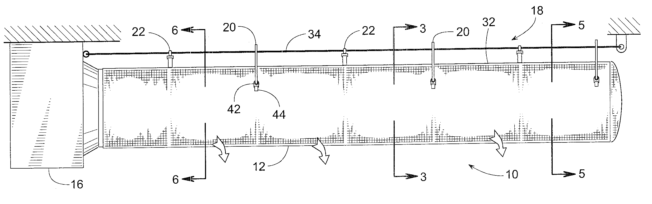
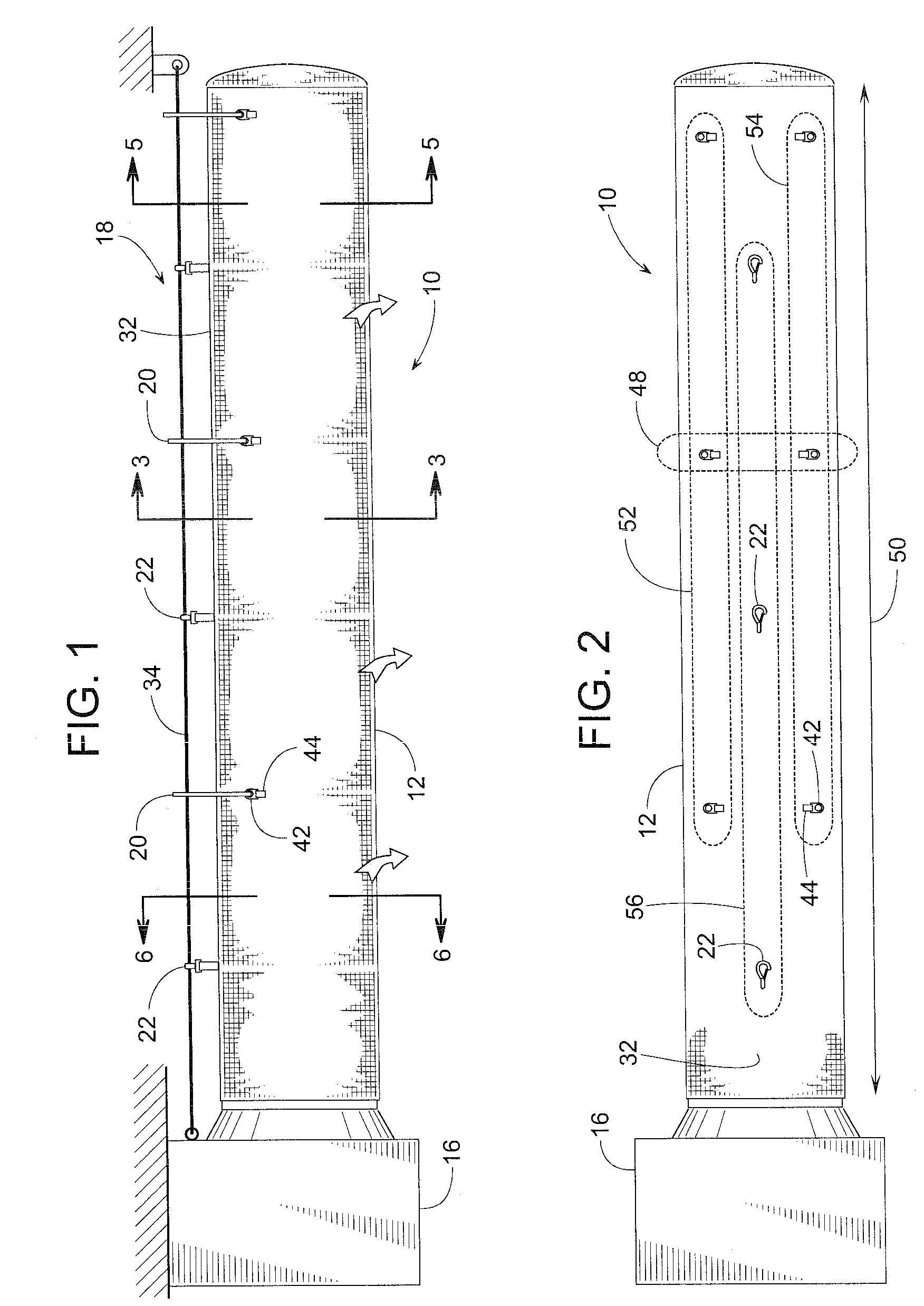
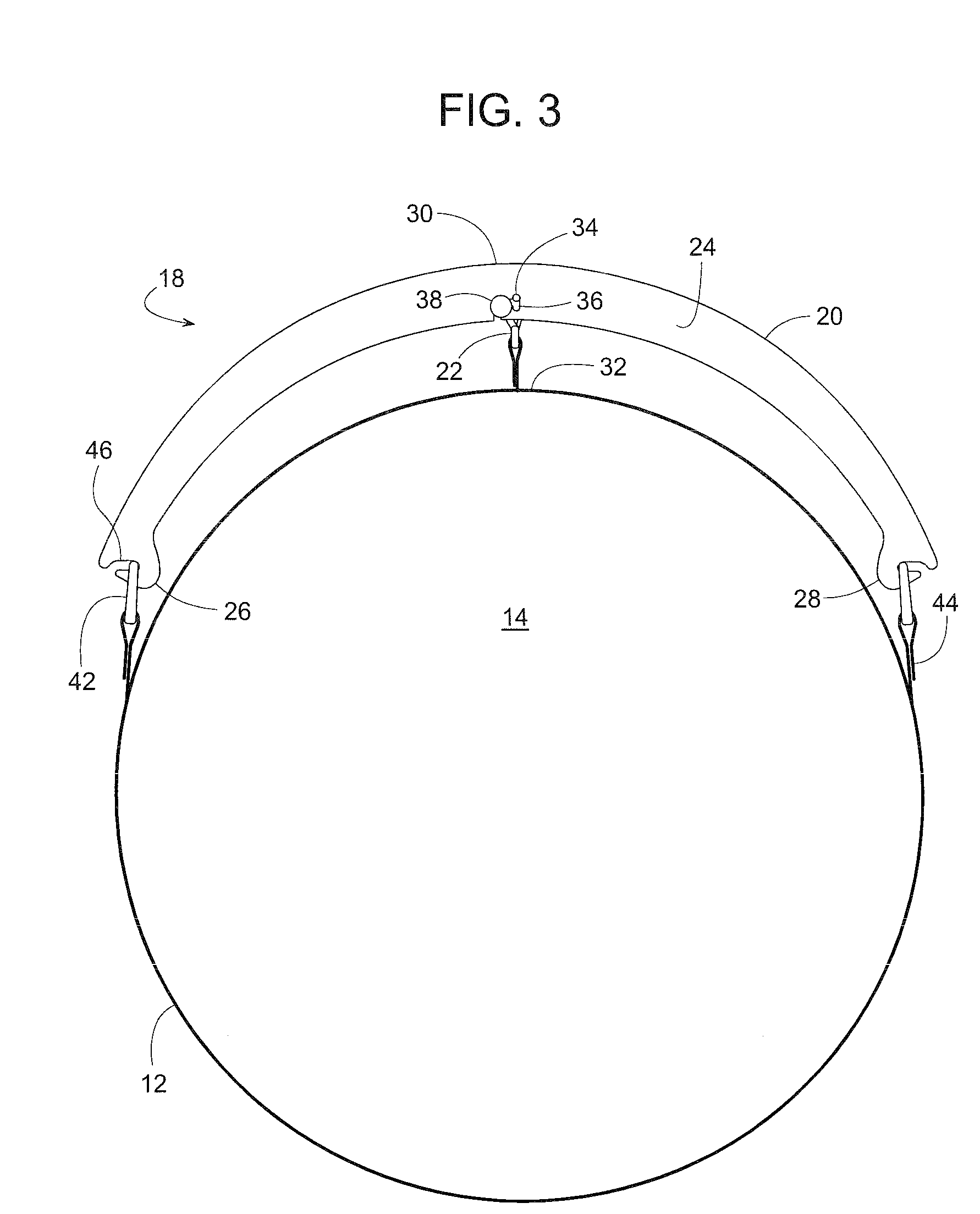
[0033]Referring to FIGS. 1-6, an HVAC system for heating, ventilating or air conditioning includes an air duct assembly 10 with an inflatable tube 12 made of a pliable material that encloses an air passageway 14. Tube 12 is connected to receive pressurized air from a blower 16 or some other source and distribute that air within a building or wherever the air may be needed. To disperse the air from within the tube's air passageway 14, tube 12 can be made of an air permeable material and / or tube 12 may be provided with a series of holes or air registers.

[0034]For the HVAC system to meet the demand for air, blower 16 can be periodically energized and de-energized as needed. When energized, blower 16 inflates tube 12 to a generally cylindrical shape (or some other closed shape) as shown in FIGS. 1, 3, 5 and 6. Once the need for air has been satisfied, de-energizing blower 16 causes tube 12 to deflate to the shape shown in FIG. 4.

[0035]As tube 12 changes between its inflated and deflated...


PUM


Abstract

An external suspension system for supporting an inflatable air duct includes a series of external hangers that help hold the duct open while the duct is deflated. In some embodiments, the suspension system supports the duct at a series of points that are broadly distributed in a staggered pattern across the duct, yet the entire duct can be suspended from a single overhead cable, even if the duct is a stepped tube with multiple diameters. The system includes novel ways of locking the hangers to the duct and to the overhead cable.

Description

FIELD OF THE DISCLOSURE[0001]The present disclosure generally pertains to inflatable air ducts and more specifically to a support system for such a duct.BACKGROUND OF RELATED ART[0002]Ductwork is often used for conveying conditioned air (e.g., heated, cooled, filtered, etc.) discharged from a fan and distributing the air to a room or other areas within a building. Ducts are typically formed of rigid metal, such as steel, aluminum, or stainless steel. In many installations, ducts are hidden above suspended ceilings for convenience and aesthetics. But in warehouses, manufacturing plants and many other buildings, the ducts are suspended from the roof of the building and are thus exposed. In those warehouse or manufacturing environments where prevention of air-borne contamination of the inventory is critical, metal ducts can create problems.[0003]For instance, temperature variations in the building or temperature differentials between the ducts and the air being conveyed can create cond...

Claims


Application Information

Patent Timeline
Patent Type & Authority Applications(United States)
IPC IPC(8): F24F7/00
CPCF24F13/0254F24F13/0218
Inventor BROWN, ROBERTGEBKE, KEVIN J.HEIM, FRANKJACOBSON, MIKEPASCHKE, NICOLAS B.PINKALLA, CARY
Owner RITE HITE HLDG CORP
Why Eureka
Try Eureka