
Dual wheel caster

a caster and caster body technology, applied in vehicle components, multi-purpose tools, applications, etc., can solve the problems of bending of the leg portion when the bed frame is being moved, failure of the caster assembly or the leg portion, and the entire bed frame is disabled, so as to increase strength, reliability, and durability.

Inactive Publication Date: 2008-05-29
FREDMAN BROS FURNITURE
View PDF20 Cites 12 Cited by
  • Summary
  • Abstract
  • Description
  • Claims
  • Application Information

AI Technical Summary

Benefits of technology

[0009]In light of the foregoing comments, it will be recognized that a principal object of the present invention is to provide a dual wheel caster which is of simple construction and design and which can be easily employed with highly reliable results.
[0010]Another object of the present invention is to provide a dual wheel caster that divides the weight being applied to the caster into two different load points.
[0011]A further object of the present invention is to provide a dual wheel caster that is capable of being manufactured using commonly available components that are relatively inexpensive.
[0014]Another object of the present invention is to provide a dual wheel caster that has increased strength, reliability, and durability.
[0015]A further object of the present invention is to provide a dual wheel caster that is not offset and does not bend or fracture.

Problems solved by technology

One of the disadvantages with such caster assemblies is that the leg portion is apt to bend when the bed frame is being moved.
This bending causes stress on the caster assembly and can lead to failure of the caster assembly or the leg portion.
If the caster assembly or the leg portion breaks or fails then the entire bed frame is disabled.

Method used


Image

  • Dual wheel caster
  • Dual wheel caster
  • Dual wheel caster

Examples


Embodiment Construction

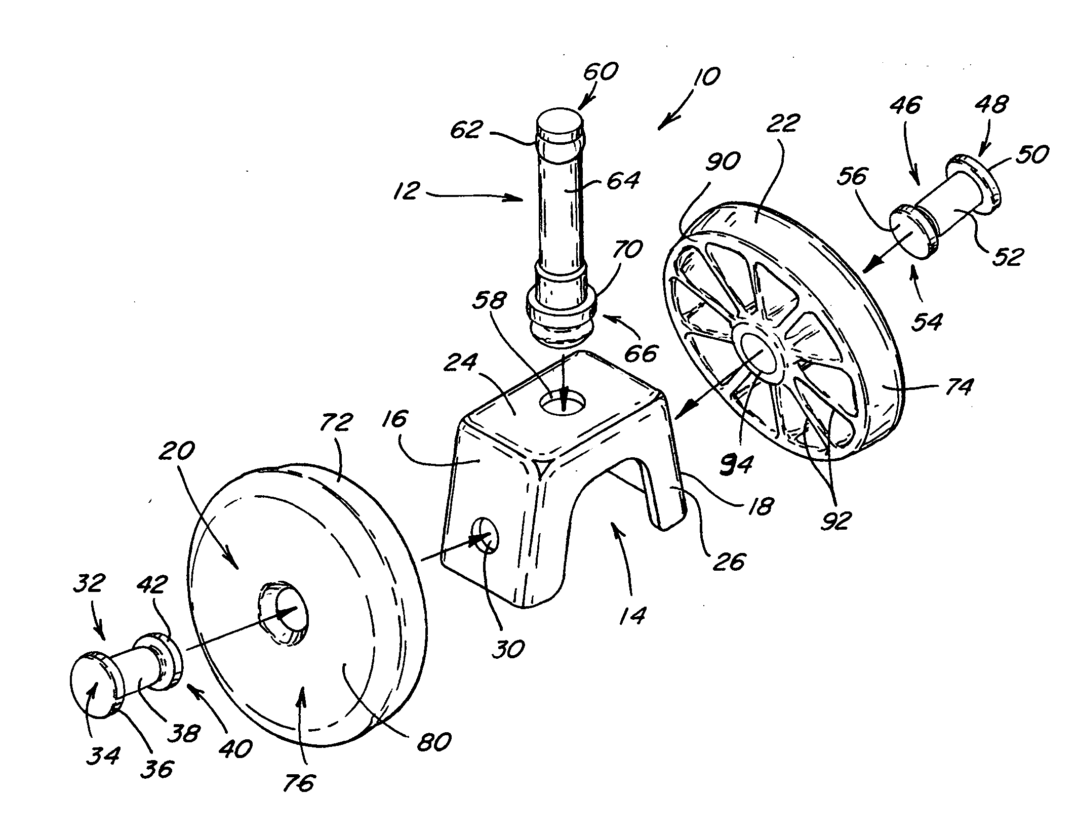
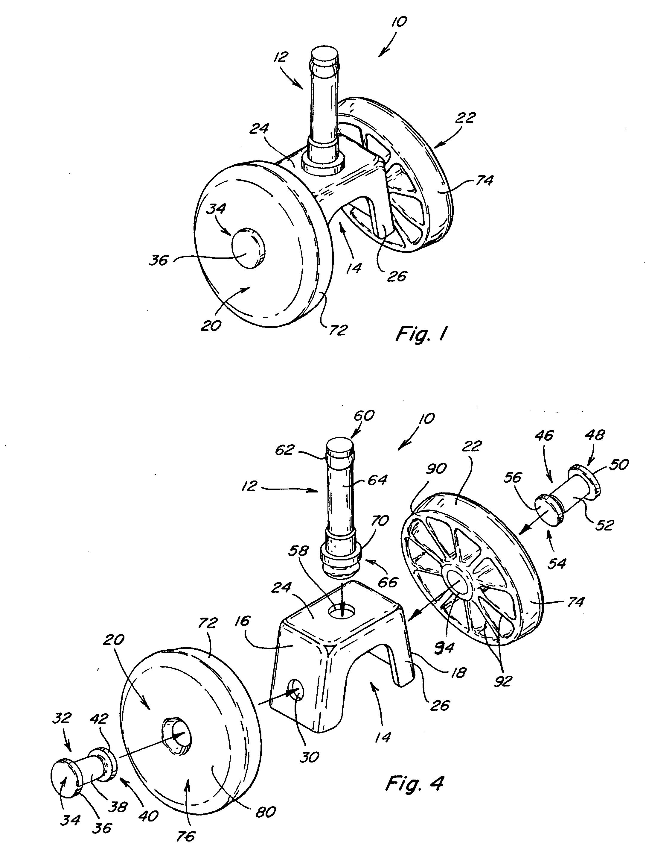
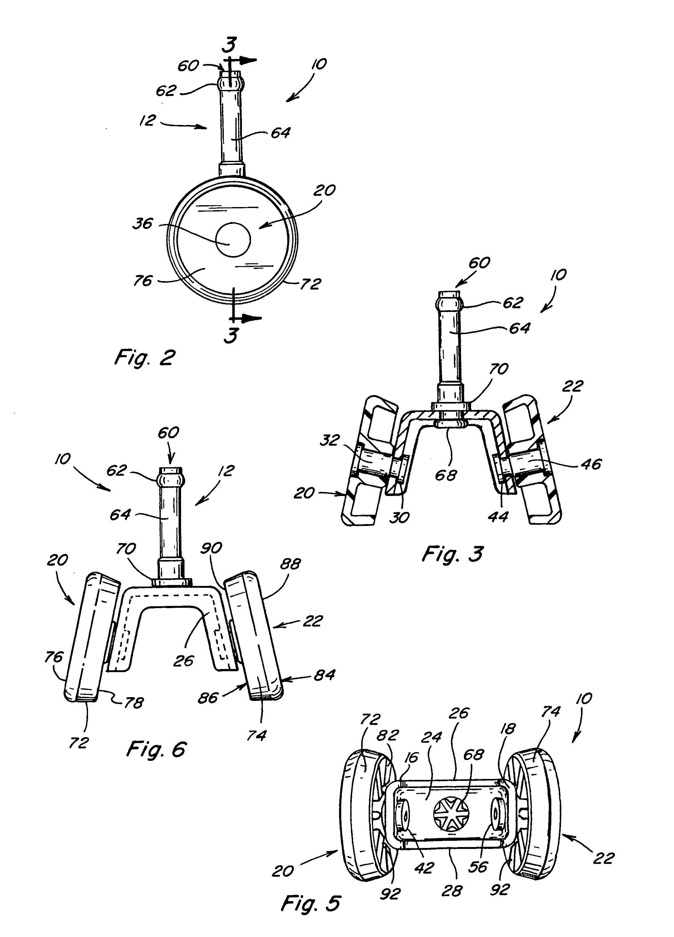
[0024]Referring now to the drawings, wherein like numbers refer to like items, number 10 identifies a preferred embodiment of a dual wheel caster constructed according to the present invention. With reference now to FIGS. 1-6, the dual wheel caster 10 is shown comprising a stem portion 12 mounted to a wheel housing or mount 14. The wheel housing 14 has a pair of opposed angled sides 16 and 18 and a pair of wheels 20 and 22 that are mounted to the sides 16 and 18, respectively. The housing 14 has a top 24 to which the stem 12 is mounted or connected. The stem 12 is centrally positioned in the top 24 of the housing 14. The stem portion 12 is adapted to fit in a socket member (not shown) that may be inserted into a frame portion (not shown) to allow the caster 10 to swivel or rotate a full 360°. The housing 14 has a front side 26 and a back side 28.

[0025]The side 16 has an opening or aperture 30 through which a pin or axle portion 32 is adapted to be inserted. The axle 32 has a first e...


PUM


Abstract

A dual wheel caster is disclosed that comprises a housing having a pair of opposed angled sides, a pair of wheels with one of the wheels being mounted to one of the angled sides and the other one of the wheels being mounted to the other one of the angled sides, and a step portion connected to the housing.

Description

BACKGROUND OF THE INVENTION[0001]This invention relates to a dual wheel caster assembly and more particularly to a dual wheel caster having a pair of angled wheels.[0002]Casters are used to support and move various equipment or structures such as furniture, chairs, and bed frames. The casters include one or two wheels and are employed to easily move or roll the structure to which the casters are mounted or attached. Generally, the casters have consisted of a central mounting member having an off-centered stem or a pintle extending up from the central mounting member. One or more wheels are mounted to the central mounting member. The stem is typically inserted into a socket plate that is fixed to a leg or other means of mounting the caster to the structure. In this manner, the caster may swivel to facilitate movement and maneuvering of the structure.[0003]In a particular application, casters have been used on bed frames for many years. A bed frame typically is constructed of various ...

Claims


Application Information

Patent Timeline
Patent Type & Authority Applications(United States)
IPC IPC(8): B60B33/00
CPCB60B33/001B60B33/0021B60B33/0042B60B33/0052B60B33/0055Y10T16/214B60B33/0073B60B2200/20B60B2200/24Y10T16/203Y10T16/1853B60B33/0068
Inventor BRYANT, FRANK
Owner FREDMAN BROS FURNITURE
Learn More