LIGHT GUIDE PLATE, METHOD OF MANUFACTURING LIGHT GUIDE PLATE AND BACKLIGHT UNIT with the LIGHT GUIDE PLATE

Inactive Publication Date: 2008-06-05
CITIZEN ELECTRONICS CO LTD
View PDF2 Cites 34 Cited by
  • Summary
  • Abstract
  • Description
  • Claims
  • Application Information

AI Technical Summary

Benefits of technology

[0027]The above-described method enables light guide plates to be mass-produced efficiently and can also be adapted for multi-product small-lot production. Light guide plates of desired size can be manufactured by merely preparing one set of forming dies.
[0028]In addition, the present invention provides a backlight unit having the above-described light guide plate and a light source set adja

Problems solved by technology

The use of a large-sized injection molding machine increases installation cost.
Furthermore, manufacture of light guide plates

Method used


Image

  • LIGHT GUIDE PLATE, METHOD OF MANUFACTURING LIGHT GUIDE PLATE AND BACKLIGHT UNIT with the LIGHT GUIDE PLATE
  • LIGHT GUIDE PLATE, METHOD OF MANUFACTURING LIGHT GUIDE PLATE AND BACKLIGHT UNIT with the LIGHT GUIDE PLATE
  • LIGHT GUIDE PLATE, METHOD OF MANUFACTURING LIGHT GUIDE PLATE AND BACKLIGHT UNIT with the LIGHT GUIDE PLATE

Examples


Example

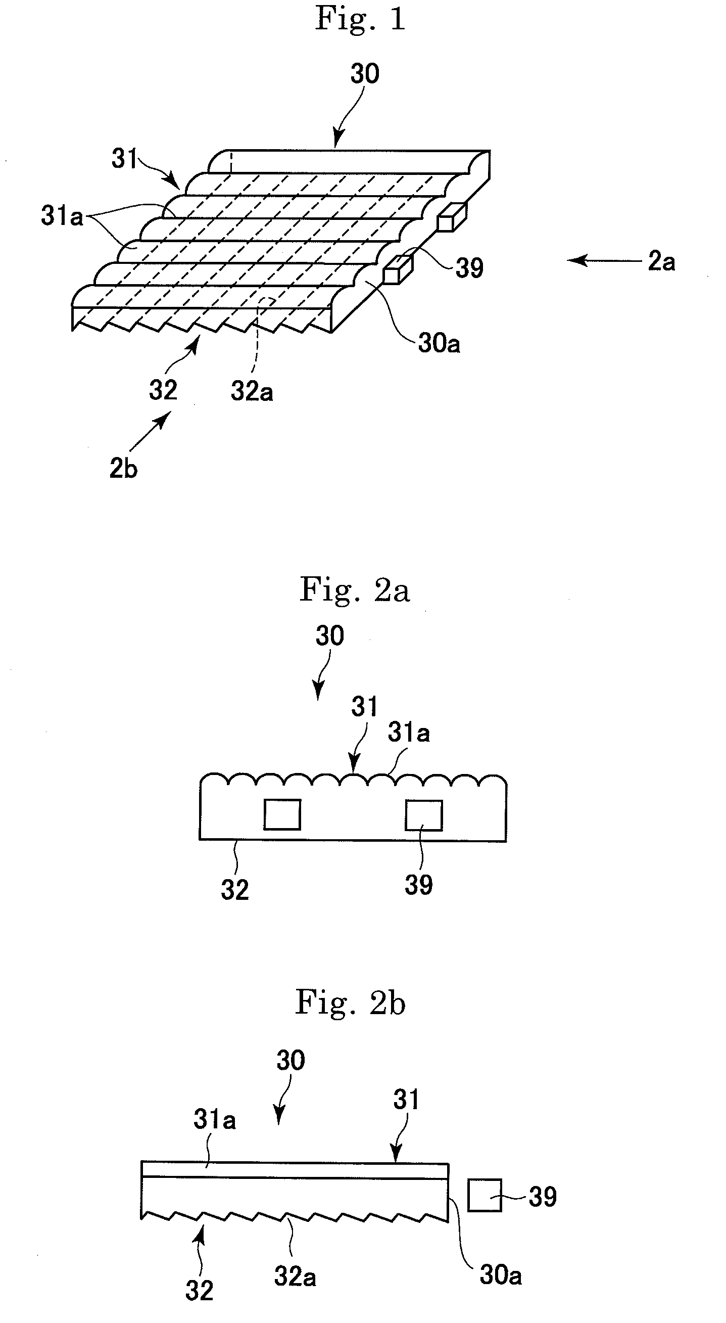
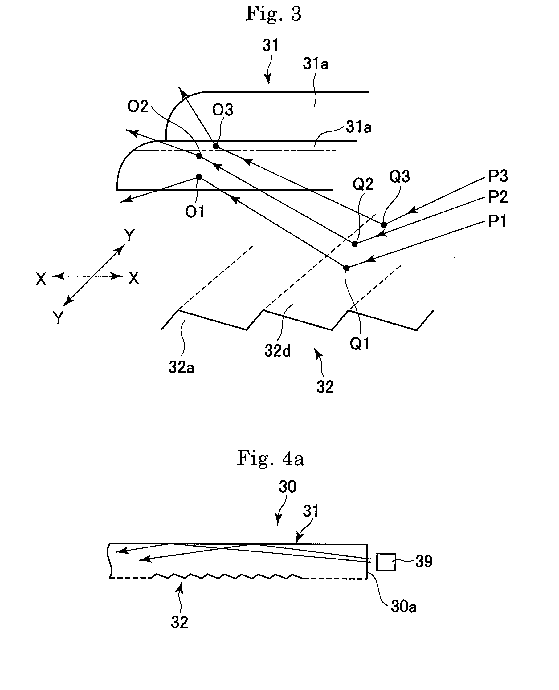
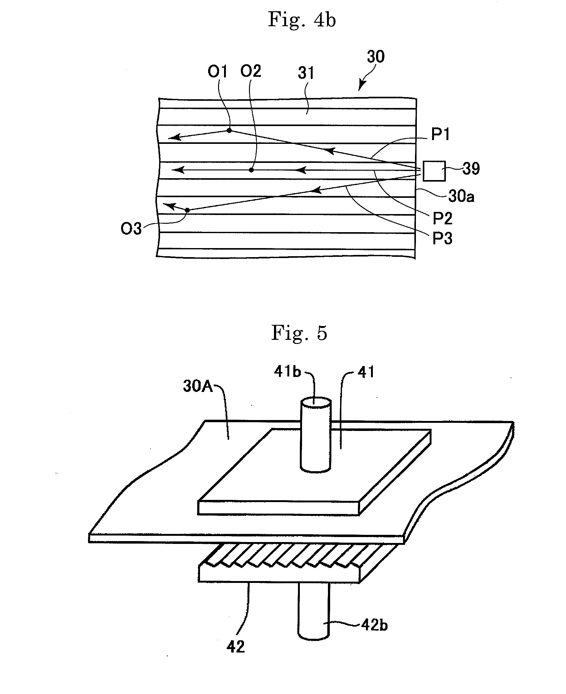
[0056]FIGS. 1 to 2b show an edge-light type rectangular light guide plate 30 according to the present invention.

[0057]The light guide plate 30 has a first surface (upper surface as viewed in the figures) 31, a second surface (lower surface) 32 opposed to the first surface 31, and four side edge surfaces extending between the peripheral edges of the first and second surfaces 31 and 32. One of the side edge surfaces is defined as a light entrance plane 30a. The first surface 31 has a series of elongated raised surfaces 31a of arcuate cross-section extending parallel to each other. The second surface 32 has a series of elongated recessed surfaces 32a of triangular cross-section extending in a direction normal to the raised surfaces 31a on the first surface 31. The light entrance plane 30a extends in a direction normal to the elongated raised surfaces 31a. The height of the raised surfaces 31a and the depth of the recessed surfaces 32a are from several μm to several tens of μm. The pitc...


PUM


Abstract

An edge-light type light guide plate (30) is provided that has a first surface (31) and a second surface (32) that are opposed to each other, and a peripheral edge surface extending between the peripheral edges of the first and second surfaces. A part of the peripheral edge surface is defined as a light entrance plane (30a). The first surface (31) has a series of parallel elongated raised surfaces (31a) of arcuate cross-section that extend in a direction substantially normal to the light entrance plane (30a). The second surface (32) has a series of parallel elongated recessed surfaces (32a) of triangular cross-section that extend in a direction substantially normal to the elongated raised surfaces (31a) on the first surface.

Description

[0001]This application claims priority under 35 U.S.C. §119 to Japanese Patent Application No. JP2006-225762 filed Aug. 22, 2006, the entire content of which is hereby incorporated by reference.TECHNICAL FIELD[0002]The present invention relates to backlight units for use in display devices such as liquid crystal display devices. More particularly, the present invention relates to a light guide plate used in an edge-light type lighting device and also relates to a backlight unit using the same.RELATED PRIOR ART[0003]Liquid crystal display devices have been widely used in personal computers, liquid crystal display televisions, electronic organizers, mobile phones, and other terminal display devices. A backlight unit is provided at the lower side of a liquid crystal display panel of such a liquid crystal display device to make the displayed image appear bright and sharp. The backlight unit often uses an edge-light type light guide plate with a view to achieving a thin backlight unit st...

Claims


Application Information

Patent Timeline
IPC IPC(8): F21V8/00B29D11/00
CPCB29D11/00278G02B6/0035G02F1/133615G02B6/0065G02B6/0038G02B6/00G02F1/1335
Inventor SHIMURA, TAKASHIOKUWAKI, DAISAKU
Owner CITIZEN ELECTRONICS CO LTD
Why Eureka
Try Eureka