Flat Battery

a battery and flat technology, applied in the field of flat batteries, can solve the problems of unstable contact between battery components, low discharge performance of batteries, and general battery designs that do not consider the operation in an environmen

Inactive Publication Date: 2008-06-05
PANASONIC CORP
View PDF1 Cites 3 Cited by
  • Summary
  • Abstract
  • Description
  • Claims
  • Application Information

AI Technical Summary

Benefits of technology

[0014]The present invention relates to a battery whose discharge performance is not deteriorated even in the case where a battery is disposed on a device to which a centrifugal force is applied in the direction in which discharge is difficult in the case of a conventional battery. A flat battery of the present invention includes a positive electrode having voids therein, a negative electrode, a separator, an electrolyte solution, and a sealed case. The negative electrode is composed of a metal including an alkali metal and is disposed facing the positive electrode. The separator is interposed between the positive electrode and the negative electrode and electrically insulates the positive electrode from the negative electrode so that they are not brought into direct contact with each other. The electrolyte solution is interposed between the positive electrode and the negative electrode in a state in which the separator is impregnated with the electrolyte solution. The sealed case contains the positive electrode, the negative electrode, the separator

Problems solved by technology

Thus, general battery designs do not consider the operation in an environment in which a centrifugal force is applied.
Therefore, in particular, when a large amount of electric current is needed, or in a low temperature environment, the discharge performance of the battery is significantly reduced.
However, the electrolyte solution is gradually decomposed to generate gas in the battery.
With this gas, a position of the electrolyte solution in the battery or contact between component

Method used


Image

  • Flat Battery
  • Flat Battery
  • Flat Battery

Examples


Embodiment Construction

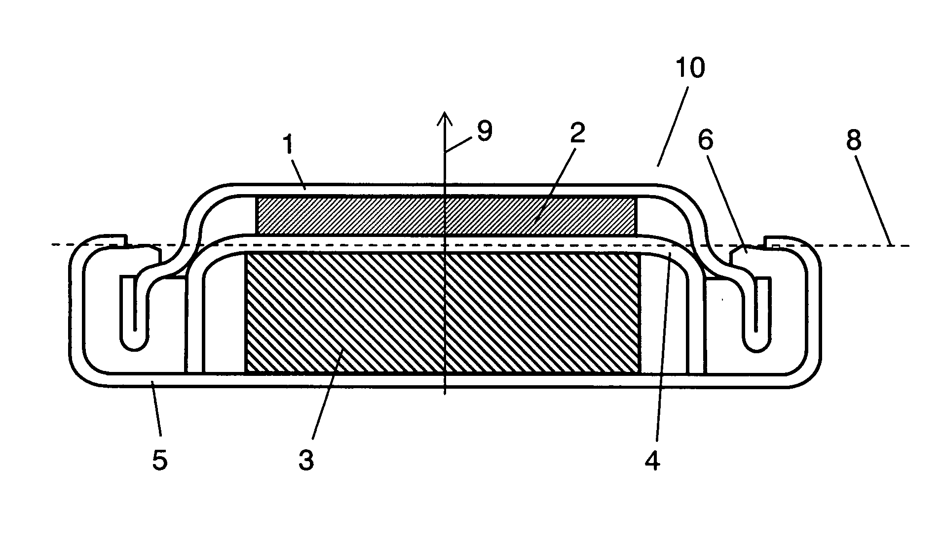
[0031]FIG. 1 is a sectional view showing a flat battery in accordance with an exemplary embodiment of the present invention. Flat battery (hereinafter, referred to as battery) 10 includes positive electrode 3 having voids therein, negative electrode 2, separator 4, an electrolyte solution (not shown), positive electrode case (hereinafter, referred to as case) 5, and sealing plate 1. Negative electrode 2 is composed of a non-pored metal including an alkali metal and is disposed facing positive electrode 3. That is to say, negative electrode 2 is made of an alkali metal or an alkali metal alloy. Separator 4 is interposed between positive electrode 3 and negative electrode 2 and electrically insulates positive electrode 3 from negative electrode 2 so that they are not brought into direct contact with each other. The electrolyte solution is interposed between positive electrode 3 and negative electrode 2 in a state in which separator 4 is impregnated with the electrolyte solution. Case ...


PUM


Abstract

A flat battery includes a positive electrode having voids therein, a negative electrode, a separator, an electrolyte solution, and a sealed case. The negative electrode is composed of a metal including an alkali metal and is disposed facing the positive electrode. The separator is interposed between the positive electrode and the negative electrode and electrically insulates the positive electrode from the negative electrode so that they are not brought into direct contact with each other. The electrolyte solution is impregnated into the separator and is interposed between the positive and negative electrodes. The sealed case contains the positive and negative electrodes, the separator, and the electrolyte solution. A volume of the electrolyte solution is larger than a space volume at the side of the positive electrode when space formed in the sealed case is divided by a plane dividing into two sections at the middle in the thickness direction thereof.

Description

TECHNICAL FIELD[0001]The present invention relates to a flat battery. In particular, it relates to a flat battery used in an environment in which a centrifugal force is applied, for example, when the battery is attached to a rotor.BACKGROUND ART[0002]In a general chemical battery, an electrochemical reaction generating electrical energy proceeds by ionic conduction in an electrolyte that is present between a positive electrode and a negative electrode. In general, a liquid electrolyte (electrolyte solution) is present in a state in which it is impregnated into a separator interposed between the positive and negative electrodes, and contributes to oxidation / reduction reactions between the positive and negative electrodes. An electrolyte solution can be roughly classified into an aqueous solution and an organic solution. Furthermore, recently, batteries using a solid electrolyte such as a polymer electrolyte have been developed.[0003]Among these batteries, a flat battery is often used...

Claims


Application Information

Patent Timeline
IPC IPC(8): H01M6/02
CPCB60C23/041H01M2/0222H01M2/0465H01M2006/5094H01M6/16H01M10/052H01M2/38Y02E60/10H01M50/109H01M50/153H01M50/70
Inventor YOSHIDA, MASAHIKOKUWAMURA, TOSHIYA
Owner PANASONIC CORP
Why Eureka
Try Eureka